What Does an Exhaust Particle Sensor Do?
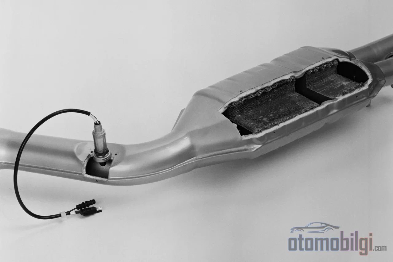
In the exhaust line of a diesel vehicle, just behind the diesel particulate filter (DPF), a pocket-sized component works silently: the particulate matter sensor, or PM sensor for short. Its job is to answer a single question: is the filter actually trapping what it is supposed to trap? While the differential pressure sensor estimates soot levels indirectly, the PM sensor measures the particles escaping the filter directly. That is why it is the most critical verification link in modern emission systems, and for most drivers the only moment it becomes visible is a warning light glowing on the dashboard.
So how does this small sensor count soot, which fault codes lie behind it, and why is the real problem usually somewhere completely different even though the sensor is often blamed? On this page, we explain the PM sensor's operating principle, its role in monitoring DPF efficiency, and the path to follow for an accurate diagnosis, step by step.
What Is the PM Sensor and Where Is It Located in the Exhaust Line?
The particulate matter (PM) sensor is an electronic device designed to monitor the concentration of fine soot and ash particles in the exhaust gas. Its basic function falls under two headings: verifying compliance with emission standards and helping the engine control unit (ECU) manage the DPF system correctly.
Its location summarizes the logic of the system in a single sentence. The sensor is typically mounted at a point downstream of the DPF, near the outlet of the SCR system. The design idea here is simple: if the aftertreatment chain is working healthily, almost no particles escape the filter and the amount of particles reaching the sensor stays at a minimum. When the sensor detects a significant amount of particles, it signals that there is a problem upstream: the filter may be cracked, melted, or not operating at the expected efficiency.
How Does the Sensor Measure Soot? The Resistance Principle Step by Step
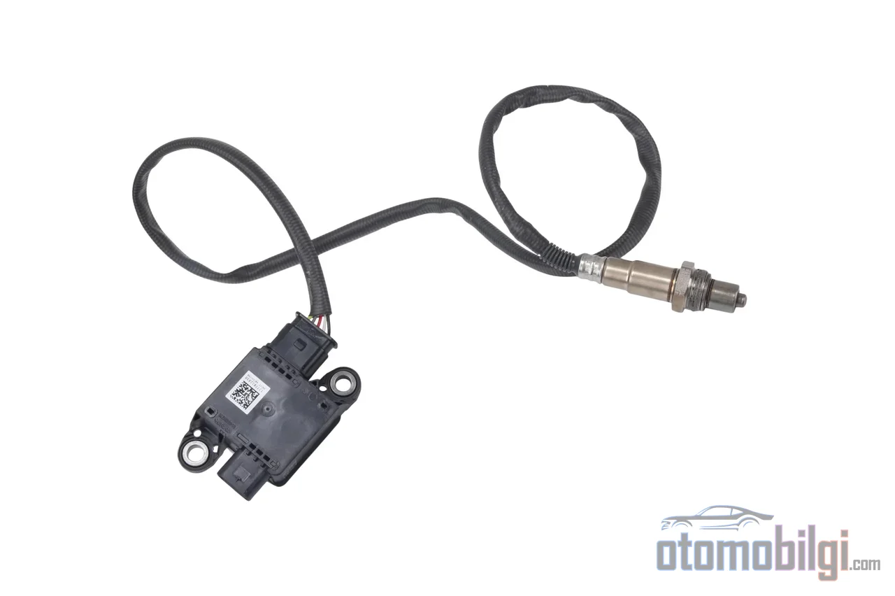
Most PM sensors in heavy-duty trucks work on the resistance measurement principle, which Bosch also uses in production. Inside the sensor there is a structure resembling the teeth of a comb, called an interdigital electrode design. The measurement cycle consists of six logical steps:
- Soot particles in the exhaust gas accumulate on the sensor electrodes.
- The accumulated soot forms conductive paths between the electrodes.
- This conduction reduces the electrical resistance between the electrodes.
- When conductivity reaches a predefined threshold value, a signal is sent to the ECU.
- The ECU initiates a regeneration cycle to burn the soot trapped inside the DPF.
- The sensor element often heats up above 600°C to burn off the soot on its own surface and is reset for the next measurement.
The sensor is configured as a smart sensor that communicates with the ECU over the CAN (Controller Area Network) bus. In many applications, instead of measuring continuous mass concentration, it reports whether an adjustable soot threshold has been exceeded. It is also used to monitor physical failures such as cracking or melting of the DPF substrate.
Alternative Approach: Electric Charge-Based Measurement
There is a second technology in exhaust applications. Soot particles in the exhaust carry a natural electrical charge; in this principle, a strong electric field accelerates the particles toward the detection electrode. The rate of charge accumulation at the electrode is proportional to the particulate matter content, and depending on its electronic architecture, the system offers a time resolution of up to 20 ms. This is an approach capable of real-time concentration measurement rather than waiting for a threshold to be exceeded.
A common confusion needs to be pointed out here: laser and infrared PM sensors that measure ambient air quality work on the principle of light scattering and are a completely different application. Exhaust PM sensors measure using electrical principles, while ambient sensors measure using optical principles; the two are not interchangeable.
Key Takeaways
- The PM sensor is mounted at the outlet of the DPF and directly measures the particles escaping the filter.
- Soot detection is based on the reduction of electrical resistance between electrodes; the sensor often resets itself by heating to above 600°C.
- Bosch PM sensors offer filter monitoring that helps reduce particulate emissions by up to 99%.
- A PM sensor fault code most often originates not in the sensor itself, but in the wiring or DPF health.
Monitoring DPF Efficiency and Its Role in Euro 6 Compliance
In Euro 6 diesel engines, DPF function monitoring is carried out through two independent channels: the differential pressure sensor and the particulate sensor. By measuring the difference between the DPF inlet and outlet pressures, the pressure sensor contributes to the ECU's soot level estimation. The PM sensor, on the other hand, directly measures the particles escaping the filter. Using these two channels together makes monitoring significantly more accurate and is common practice in Euro 6 diesel engines.
This monitoring also has a legal dimension. Monitoring the filtration efficiency of the DPF is an explicit regulatory requirement for minimizing PM emissions. Within the framework of US legislation, the OBD system in heavy-duty vehicles must be able to detect a DPF failure that leads to particulate emissions of 1.5 times the emission limit (approximately 4.9 mg/m³). The electronic PM sensor has been proven to measure concentrations below 1 mg/m³; in other words, it offers a resolution well above the sensitivity required by the legislation.
There is an empirical correlation between the sensor voltage and the particulate concentration in the exhaust, depending on the applied voltage and exhaust flow rate. The sensor also verifies the success of regeneration: if the sensor still detects particles after regeneration, the cleaning cycle has not produced the desired result.
The Gasoline Side: GPF and Expanding Scope
Particulate monitoring is not only an issue in the diesel world. Gasoline particulate filters (GPF) have been developed to control the particulate emissions of gasoline direct injection (GDI) engines. These are mounted close to the catalytic converter, or integrated into it, as wall-flow ceramic honeycomb filters. An interesting engineering detail: GPF filtration efficiency increases over its lifetime thanks to ash accumulation. Under Euro 5-6, particles larger than 23 nm are counted, while with Euro 7 this threshold drops to 10 nm; meaning the requirement for monitoring precision is constantly rising. Under Euro 7, non-exhaust emission limits for brakes and tires as well as battery durability rules have also come into force, and greater emphasis is expected on monitoring real-driving emissions compliance on board the vehicle (on-board monitoring).
What Symptoms Does a Faulty PM Sensor Give?
When the sensor or the relevant purification component fails, the picture is usually clear: the engine malfunction lamp (check-engine) or emissions warning lamp lights up, and a fault code related to the PM sensor or DPF is stored in the ECU. This condition is most often seen together with driving performance problems. A faulty soot sensor; creates a chain of problems ranging from a drop in engine performance to serious difficulties in diagnosing the DPF system. A sensor that measures incorrectly can trigger unnecessary regeneration and increase fuel consumption, because the system's decisions about DPF performance are based on this measurement.
The Most Critical Point: The Code Does Not Always Blame the Sensor
The most expensive mistake in service practice is made here. A PM sensor fault code does not mean the sensor is broken; the code often reports a problem located elsewhere. For codes such as P103400, P24D000, U02A300 and P1033, the wiring and power supply should be checked first: the sensor is rarely the culprit. For codes related to the heater circuit (for example P24FC00), the heater circuit should additionally be tested. For internal fault codes, DPF health must be verified before replacing the sensor, and the ECM software must be updated after the replacement. Genuine internal failures do of course exist and have been recorded as the primary failure mode; but replacing the sensor without properly establishing the diagnostic chain reproduces the problem instead of solving it.
Maintenance, Cleaning and Correct Replacement
Directly cleaning the sensor element is generally not recommended. The element is fragile and has a self-cleaning design; heavy soot accumulation on the sensor is most often a sign of a DPF problem, not a sensor problem. There is also a structural detail that requires attention: the PM sensor consists of a probe and a module, and these two parts cannot be replaced separately; the unit must be replaced as a whole.
During installation, adhering to engineering tolerances is critical:
- the protective cap shielding the fragile ceramic element must remain in place until the sensor is fully seated.
- The manufacturer's torque value must be applied; a typical value is within the range of 50 Nm ± 5 Nm.
- A 22 mm oxygen sensor socket should be used for removal and installation, and the sensor must not be lubricated with anti-seize compound.
- A sensor that has been dropped or makes noise when shaken (a sign of internal damage) must never be installed.
The step after replacement is as important as the installation itself: without an ECM software update, the sensor cannot be expected to operate with correct calibration. The entire system the sensor is connected to also requires regular maintenance; most manufacturers recommend cleaning the DPF every 1,000 hours of engine operation, and in some applications this interval can drop to as little as 6 months. To take an in-depth look at DPF maintenance, check out our DPF guide, and for the other monitoring components in the system, visit our lambda sensor page.
What Does the PM Sensor Do? Short and Clear Answer
Now that all that context is out of the way, let's get to the heart of the question. The PM sensor is a monitoring component mounted at the outlet of the DPF that directly measures the soot and ash particles escaping the filter, detects particle accumulation through the change in resistance between electrodes, and feeds the ECU's decisions on both regeneration and emissions compliance. In Euro 6 diesel vehicles, it works to verify DPF function and serves as the primary safety net in the exhaust line, alongside the catalytic converter and the SCR system.
The practical takeaway for the driver can be summed up in three sentences: When the warning light comes on, first have the fault code read, don't replace the sensor without verifying the wiring and DPF health, and don't attempt to clean the sensor yourself. A correct diagnostic chain protects both your wallet and your exhaust system.
Sources
- Your Essential Guide to Particulate Matter (PM) Sensors
- Particulate matter sensor - Bosch Mobility
- Development and Demonstration of an Electronic Particulate Matter Sensor (DEER 2009) - US DOE
- Soot (PM) Sensors - DieselNet
- Diagnosing the Soot Sensor (PM-sensor) - DiagnoseDan
- How does a particulate matter sensor work? - Forté Lubricants
- Characteristics of Resistive PM Sensors for Onboard Monitoring - MDPI