Why Does the Inverter Need Its Own Cooling?
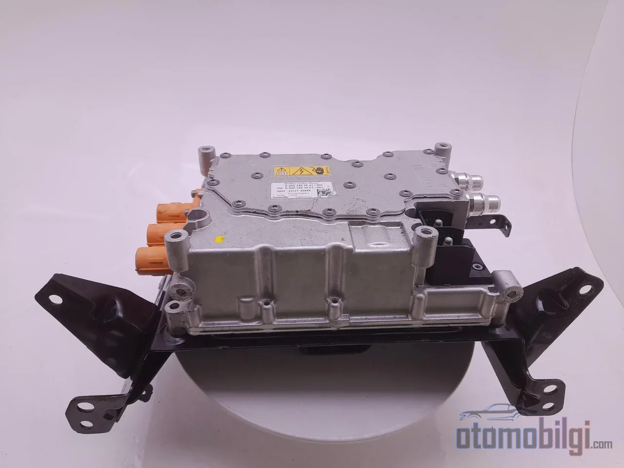
In an electric car, the element that limits power when you floor the throttle is often not the motor itself, but the small box sitting next to it. A speed cap that appears out of nowhere, a DC fast charging session that slows down in the summer heat, power loss felt on a long climb: The common name for these symptoms is usually thermal derating, in other words the inverter's own protection mechanism. So if the motor can withstand hundreds of degrees, why must the power electronics feeding it live within a much narrower thermal window?
The answer is hidden in the millimeter-scale semiconductor modules inside the inverter. These switching devices, called IGBTs and SiC MOSFETs, convert the battery's direct current into the three-phase alternating current the motor needs by chopping and combining it thousands of times per second. In every switching cycle, some energy turns into heat, and that heat concentrates within a silicon chip of just a few square millimeters. This is one of the smallest, most expensive and thermally most fragile components of the vehicle.
Why Does the Inverter Get So Hot?
The inverter's basic job is energy conversion: Turning the DC voltage from the battery into AC at the frequency and amplitude that match the motor's rotational speed and torque demand. During charging, the same power electronics chain works in reverse; the AC taken from the grid is converted into DC to be sent to the battery, and the two functions are usually combined within a single unit. Losses occur at every step where the voltage is stepped up or down.
All of these losses turn into heat, and every component in the power conversion chain, from the transistors to the driver circuits and the microcontroller, must be cooled. Among the power electronics units in a vehicle, the inverter is the most critical stage in terms of the heat load it generates. Since high voltage and high current are switched simultaneously, the drive inverter, known as the traction inverter, is the most demanding customer of the vehicle's thermal management.
The critical point is this: The motor, with its copper windings and steel core, is a relatively thermally tolerant machine. In the inverter, however, the power module's operation takes place on a chip of only a few square millimeters, and the heat must pass through the bond wires, solder layers and the cooling plate adjacent to the chip. Different physics means different limits.
Key Highlights
- Typical SiC MOSFET and diode modules have a maximum junction temperature in the range of 150-175 °C.
- In industrial converter designs, 125 °C is recommended as a design temperature with a reasonable margin.
- Rising ambient temperature reduces the fast charger's heat dissipation capacity, limiting performance.
- With the transition to 800V architectures, the thermal management of SiC inverters has become one of the most challenging engineering problems in EV design.
Junction Temperature: Where Is the Real Limit Drawn?
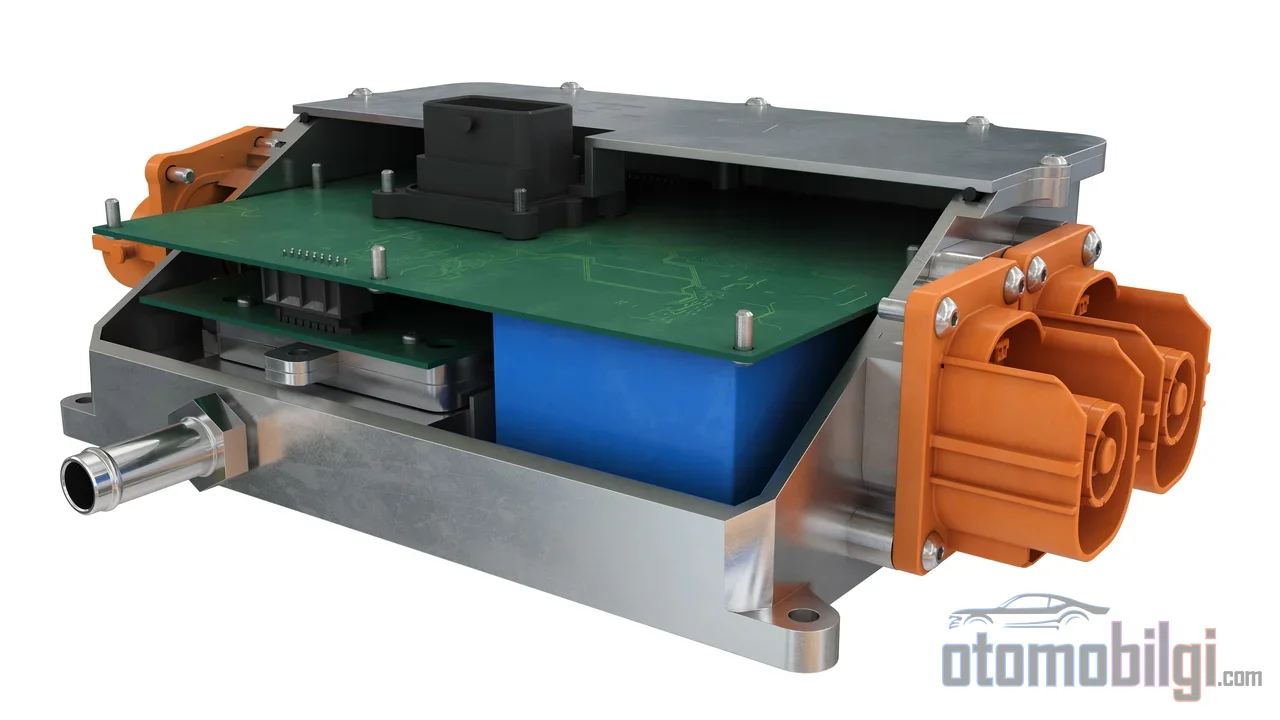
The critical measurement in power semiconductors is not the external casing but the junction, meaning the internal temperature of the semiconductor chip itself. The Tj value in datasheets refers to the ceiling that this chip can withstand. In typical SiC MOSFET and diode modules, this ceiling is in the 150-175 °C range. Some analyses mention a higher ceiling value, such as 200 °C, for SiC inverters; but this figure should not be read on its own, because the ceiling value and the continuous operating point are not the same thing.
The engineering subtlety here is this: A junction value such as 175 °C is the upper limit the device can tolerate for a short time; it is not the permitted point for hours of continuous operation. Designers make their steady-state calculations well below this ceiling. In industrial converter designs, 125 °C is a common design target that leaves a reasonable margin to the maximum operating value. The reason lies in wear-out mechanisms: When the junction temperature is kept continuously close to the ceiling, the wear of the bond wires connecting the chip to the package accelerates, and the module's lifetime shortens noticeably.
Thermal Difference Between IGBT and SiC
Classic silicon IGBTs are rated in the 1.2 kV class and compete with SiC MOSFETs in the same voltage class. However, silicon's electrical resistance and thermal conductivity properties force IGBTs to routinely operate close to their temperature limits; this narrows the design margin. Silicon carbide's thermal conductivity is roughly three times that of silicon, which means more comfortable heat dissipation for the same losses. Yet SiC's superiority does not come free of charge: The production cost of SiC substrates is still considered one of the main brakes on the transition.
Derating: Why Does Power Curtail Itself?
When the junction temperature approaches the safe operating limit, the inverter does not shut down the circuit; first it acts wisely and automatically reduces the output power. This protective mechanism is called derating, that is, power reduction. When the temperature returns to the safe zone, the power comes back too. In the driver's eyes, this is not a sudden failure; the temporary inability to deliver peak power is the vehicle responding to the accelerator pedal's demand in a more restrained manner for a while.
This limit is not just a theoretical possibility. In the lower parts of the driving frequency range, when high torque is demanded at low engine speed, the risk of junction temperature being exceeded increases, and inverter manufacturers have to limit the current capacity of the semiconductors in this region. The power restriction felt at launch and under heavy load is often the result of this limit. In response to temperature data, the inverter output can be reduced, and in advanced cases the unit can shut down completely.
An important distinction also comes into play here: Most of the "inverter overheated" cases reported by drivers are actually not permanent damage, but protective derating. When the vehicle cools down, performance recovers on its own. If the temperature is not managed, the consequence is more serious: An uncontrolled thermal runaway can develop, and this turns into a safety issue that could harm both the vehicle and the systems around it. Derating exists precisely to never let that point happen.
The Hidden Thermal Account of Fast Charging
During DC fast charging, the thermal stress is not applied only to the battery. Battery thermal and power electronics thermal are two layers that must be kept separate; our subject here is the latter. High ambient temperature reduces the converter's heat rejection capacity, increases losses, and narrows the operable thermal margin. The result is that the charger and the vehicle-side converter chain reduce their power. This is one reason why the charging curve softens earlier than expected in summer heat.
The 800V architecture further increases the weight of this equation. Higher voltage and faster charging rates impose additional thermal load on the battery and surrounding systems; the thermal management of 800V SiC inverters is described as one of the most challenging engineering topics in today's EV design. While the market share of 800V systems is projected to reach 45 percent in 2026, it is noted that legacy thermal materials are reaching their thermal endurance limits in SiC inverters shifting toward high power density. In other words, the architecture is accelerating, and the heat problem is growing along with it.
Cooling Hardware: Cold Plate, TIM, and Heat Path
The inverter's thermal savior is the liquid-cooled plate mounted beneath it, the cold plate. These plates enlarge the coolant's heat surface with specially machined flow channels and extended fins; cast coolers are also used for cooling IGBT modules. Design does not end with just removing heat: Even distribution of flow across the plate surface, reducing thermal resistance, optimizing pressure drop, and leak resistance are the fundamental criteria of the cold plate development process. In dual-motor architectures carrying two inverters per vehicle, series and parallel liquid circuit options are selected by balancing these criteria.
The Role of Thermal Interface Materials
Heat cannot pass from the chip to the cooling plate with direct metal contact; micro-gaps interrupt the path. Thermal interface materials that fill these gaps, i.e. TIMs (thermal pads, grease, gap fillers), complete the heat path between the heat-generating device and the cooling component, increasing both power capacity and reliability. In a typical power module package, a grease layer or baseplate forms the interface with the heat sink. The thermal resistance of the TIM layer largely determines the maximum temperature that power electronics can reach; in other words, a material layer of millimeters decides how many kilowatts of continuous output the inverter can deliver. TIMs based on copper, silver, aluminum, carbon, and polymers can reach high thermal conductivity values.
Why Not the Same Circuit as the Motor?
Motor cooling offers options such as air cooling, liquid cooling, and evaporative cooling; the motor's thermal profile is broad and flexible. The inverter, however, demands a narrow and precise window. The two power systems carry very different load profiles, and independent cooling circuits allow the control computer to send just the right amount of flow to each. A single-circuit approach would mean placing the overlapping and mutually suffocating demands of the two components in the same basket. It has also been shown that water-cooled inverters are more efficient, and two-phase cooling solutions further boost performance. In interface solutions using phase-change materials, thermal impedance is reported to decrease by more than 50 percent compared to traditional thermal paste, depending on the material.
Short Answer: Why Does the Inverter Want Its Own Cooling?
Because the power semiconductors in the inverter operate within a much narrower thermal window compared to the motor: When the junction temperature is continuously kept close to its 150-175 °C ceiling, the module wears out, and uncontrolled temperature rise turns into a safety risk. Liquid-cooled cold plates, thermal interface materials, and the derating mechanism together form the system that protects this narrow window throughout the vehicle's life. Temporary power restrictions during driving and slowdowns during fast charging are often the visible face of this protection; it is not a fault, but the very essence of the design.
The period ahead will make this window even more critical: Between 2026 and 2031, the SiC MOSFET segment is expected to expand in the EV powertrain and inverter market with a compound annual growth of 19.34 percent. Work on device design, packaging, temperature monitoring, and active thermal management aims to take the inverter's thermal resilience one step further with tools such as AI-powered real-time temperature prediction. More powerful vehicles demand stricter thermal discipline.
Sources
- The importance of inverter cooling for electric vehicles
- Mitigation of the Performance Derating in SiC Motor Drive Systems
- SiC-MOSFET or Si-IGBT: Comparison of Design and Key Properties
- The Switch from IGBTs: SiC MOSFETs Whitepaper
- Impact of extreme climatic conditions on fast EV charger performance
- 800V SiC Thermal Management Explained
- Advances in Cooling Technologies for Electric Vehicle Motors and Inverters
- Thermal Management for EV Power Electronics 2024-2034
- Inverter temperature protection and reduced EV drive power
- Inverter Overheating: Temperature Range, Derating and Fixes