What Does a DC-Link Capacitor Do in an Inverter?
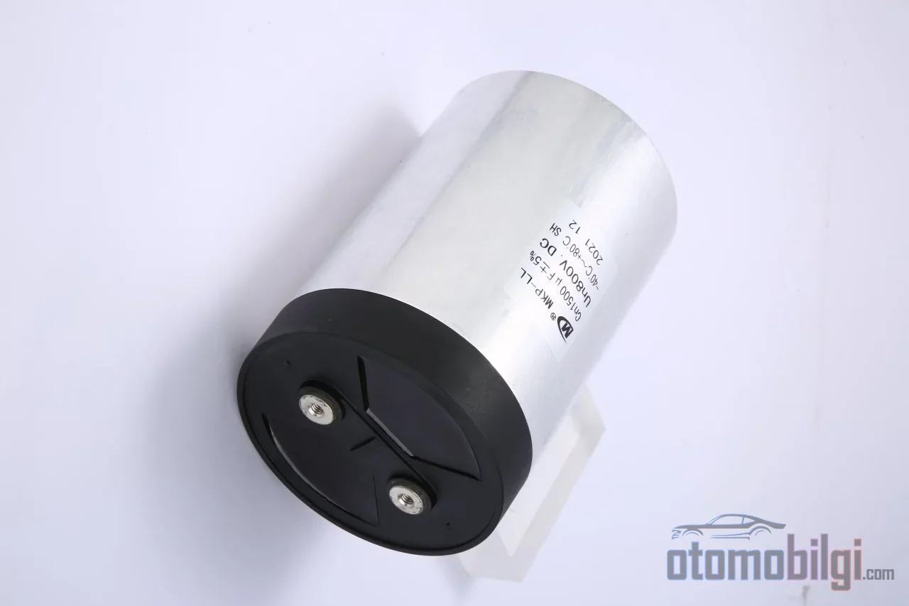
Under the hood of an electric vehicle - or more precisely, often in the power unit beneath the floor - there is a component sitting quietly along the path from the battery to the motor: The DC-link capacitor. Hearing about its job sounds rather ordinary; it smooths the voltage, filters the current. But here is the interesting part: This passive component can occupy nearly half of the traction inverter package and account for more than a fifth of the inverter's cost. It is no coincidence but a necessity that a one-time passive component takes up so much space in a power electronics center where hundreds of thousands of switching operations are performed every second.
Although the question of what the DC-link capacitor does in the inverter may seem like a one-sentence answer at first glance, it is actually the same thing as understanding the entire operating logic of the inverter. This component carries the voltage between the battery and the switching power electronics - and this voltage stands at the center of many topics, from failure symptoms to the design changes brought about by wide bandgap semiconductors.
The Buffer Reservoir Between the Battery and the Switching World
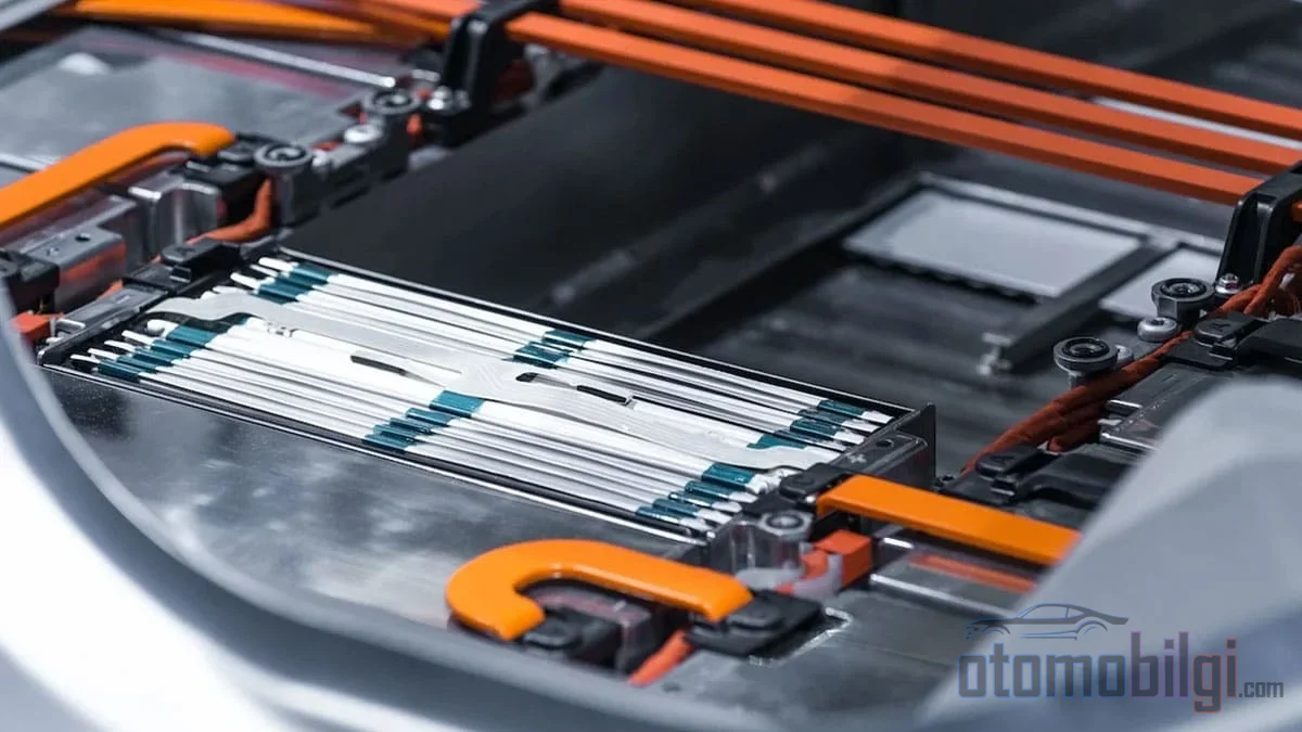
It is useful to think of an electric vehicle's power transmission chain as a two-ended tension. At one end is the battery: a DC voltage source that is as stable, balanced, and steady as possible. At the other end is the inverter: a converter where switches such as IGBT or SiC MOSFETs open and close at frequencies of tens of thousands of hertz, converting the battery's DC power into three-phase AC for the motor during acceleration, and converting the AC produced by the motor back into DC during braking. These two worlds are diametrically opposite in nature. The DC-link capacitor is placed precisely in the middle of this opposition.
The capacitor has three basic functions. The first is decoupling: It resolves the parasitic inductance effects created by the cables and connectors between the battery and the inverter. The second is providing a low-impedance path: High-frequency current components arising from switching prefer the path of low impedance - the capacitor becomes this path, and the main source of high-frequency fluctuation current, that is, the ripple current, circulates here. The third is voltage stabilization: It suppresses transient voltage spikes caused by switching and keeps the voltage as constant as possible on the DC bus.
The common denominator of these three functions is a simple physical fact: Switching power electronics demands current at a speed that its source can never provide. The capacitor is the buffer reservoir that meets the short-term load of this demand by storing it. By balancing inductive effects, it also protects the subsystems from voltage spikes, surges, and electromagnetic interference.
Highlights
- The DC-link capacitor can account for approximately 50% of the traction inverter package and more than 20% of the inverter's cost.
- Capacitance typically ranges between a few hundred µF and several thousand µF; it is sized according to output power.
- The typical rated lifetime of an aluminum electrolytic capacitor is 1,000-15,000 hours; lifetime varies exponentially with temperature.
- An empty capacitor acts like a short circuit when the ignition contacts close; therefore a pre-charge circuit is mandatory.
What Is the Capacitance Sized Based On?
Sizing is a strong function of the inverter's switching frequency and the intervals between current pulses. The faster the switch operates and the shorter the gap between current pulses, the less energy the capacitor needs to store. The designer's goal is to find the minimum capacitance that can handle the pulses without exceeding the allowed voltage fluctuation - in practice, a few percent of the bus voltage. This optimum is critical both in terms of volume and cost: Too much capacitance means unnecessary mass and cost, while too little means excessive ripple and premature aging.
In practice, values range from a few hundred microfarads to thousands of microfarads and grow with output power. Since reaching these capacitance values with a single component is not always possible, designers build capacitor banks by connecting multiple capacitors in parallel. In addition, MLCCs can be used in parallel with film and aluminum electrolytic capacitors and placed closer to the switching device; this creates an even shorter low-impedance path for high-frequency components.
To make the space the size takes up more concrete: A study on a traction inverter calculated that the DC-link capacitors take up almost half of the inverter package and account for more than 20% of its cost. That is why capacitance minimization, together with ripple-reducing control strategies, is an active area of research. Shrinking the capacitor is one of the most direct ways to increase the power density of the inverter.
Pre-Charge: The Capacitor's First Seconds
The least talked about but most critical moment for the DC-link capacitor is the moment the vehicle first moves. When the load is not active, the capacitor is empty - that is, uncharged. When the ignition contacts close, an empty capacitor behaves almost like an instantaneous short circuit. For example, connecting an 800V battery directly to an empty 1000µF capacitor produces an extremely high inrush current, and this current can damage the cables, connectors, and fuses. Therefore, before powering the high-voltage load, the capacitor must be filled gently - that is, pre-charged.
The traditional solution consists of a pre-charge contactor and a current-limiting resistor. To give an example calculation: For an 800V battery, 1000µF capacitance, and a pre-charge target of 150ms, a resistance of at most 50Ω is required; during the process, the average power reaches 1925W, and the peak current is at the 16A level. The pre-charge time is expected not to exceed 400ms. The resistor consumes significant power during those seconds; which is precisely why alternatives are being developed. Isolated key drivers, active pre-charge controllers, discrete or bidirectional DC-DC converter-based solutions, and integrated designs that respond within milliseconds are all trying to retire the traditional contactor-resistor pair - because the traditional design is the option with the lowest power density and the highest component cost.
Electrolytic or Film? The Real Balance of the Comparison
Two main technologies compete in the DC-link capacitor: aluminum electrolytic and film. The choice is a trade-off within the cost-volume-lifetime triangle, and the industry as a whole has not yet leaned entirely to one side.
| Feature | Aluminum Electrolytic | Film |
|---|---|---|
| Capacitance / energy density | High per unit volume | Lower |
| Ripple current withstand | More limited | High |
| Expected lifetime | Typically 1,000-15,000 hours (rated) | Longer |
| Size and weight | Compact | Larger and heavier |
| Usage trend | The most common type in motor drives | Its share is growing in EV applications |
Where the electrolytic wins is clear: Capacitance per volume. If you want to achieve the same capacitance with film, you spend more space and weight. Where film wins are more numerous: long lifetime, high ripple current capability, and a contribution to inverter efficiency. High ESR - that is, internal series resistance - converts ripple current directly into heat and leads to premature aging; a capacitor with low ESR reduces this energy loss and, consequently, the need for cooling. Meanwhile, beyond these two poles there is a hybrid approach: using MLCCs in parallel with film and electrolytic parts takes advantage of each technology's strong frequency region.
How Does Heat Eat Lifetime?
A capacitor's lifetime is the sum of three variables: applied voltage, ripple current, and especially temperature. The typical rated lifetime of aluminum electrolytic capacitors is between 1,000 and 15,000 hours - roughly 0.11 to 1.71 years. These numbers, which hardly seem to promise decades in a vehicle, reflect rated conditions: when voltage and ripple stay within certain limits and temperature is kept below the rated value, lifetime extends significantly. Failure does not begin suddenly, but as a slow drift: Electrical characteristics change, leakage current increases, capacitance drops, and internal heating grows. This cycle feeds itself - increasing internal heating means faster aging, and faster aging means more heating.
The practical result is a rule engineers learned long ago: Keeping the capacitor temperature below 85°C with advanced cooling techniques maximizes both lifetime and performance. This is the concrete manifestation of thermal management on the power electronics side, and it affects the inverter's mechanical architecture from capacitor placement to cold plate design.
What Happens When It Fails?
Semiconductor failures are often dramatic; capacitor failure does its work stealthily. As capacitance drops, ripple can no longer be filtered, voltage fluctuation on the bus grows, and internal heating increases. If the vehicle keeps running without the fault being noticed, the damage doesn't stay in the capacitor: It can spread to the switching elements and other components. Reliability studies emphasizing that the performance of the DC-link capacitor largely determines the performance of the entire electric drive system are not without reason for this. Practical approaches in fault diagnosis are based on monitoring the rise of the bus voltage, the pre-charge path, and the moment the main contactor closes; the capacitor's electrical signature is most readable at these moments. On the driver side, the symptom is usually indirect - sudden power losses, warning lights, or erratic behavior under load; the root cause is the aging process inside the component.
How Is the Capacitor Changing in the Age of SiC and GaN?
The biggest shift in power electronics today is moving from silicon toward wide bandgap semiconductors - SiC and GaN. GaN's bandgap of 3.4 eV is roughly three times that of silicon; these semiconductors can operate at higher voltages and higher temperatures and switch much faster. Compared to conventional silicon, they offer higher power density and efficiency. When the switches speed up, everything changes: As switching frequency increases, the gap between current pulses shortens, and theoretically the energy the capacitor must carry decreases.
But there is another side to the coin. Fast switching demands an even faster response from the capacitor - lower impedance and lower inductance. While SiC and GaN are being discussed, views stating that the DC-link is the overlooked bottleneck are not without reason: No matter how powerful the switch is, a DC-link that cannot supply current at low impedance restricts the entire system. Therefore, in future inverters the question is no longer just whether there will be less capacitance or a different technology mix; the answer will most likely be both.
Conclusion: The Value of the Invisible Buffer
The short answer to the question of what the DC-link capacitor does in the inverter is this: It stores the direct current coming from the battery before switching, smooths out fluctuations in the DC bus voltage, and by providing a low-impedance path for high-frequency ripple current, it absorbs the electrical stress that switched power electronics create every second. Without this buffer depot between the battery and the switches, it would have been impossible to bring the inverter's two worlds together on the same line.
The workload this passive component carries - half the volume of the inverter and more than a fifth of its cost - is proof that it works correctly as long as it stays in the background. The critical variables for the designer are clear: allowable ripple voltage, switching frequency, and thermal management. For the user, the takeaway is a single sentence: Before praising the motor, the battery, or the SiC MOSFETs, one must remember the capacitor that keeps them at peace on the same line.
References
- DC-Link Capacitors in Electric Vehicles
- DC-Link Capacitor Pre-Charge Designs in Automotive Systems
- Inverter DC Link Capacitor Selection
- Modeling of DC Link Capacitor Current Ripple for Electric Traction Drives
- Reliability study on DC-link capacitor in fault states of VSI
- The Roles of Capacitors in EV Traction Inverter Topologies
- What is a DC Link Capacitor?
- Performance and benefits of GaN versus SiC
- Looking Closer At DC Link Capacitors In Electric Vehicles