PWM in the Inverter: How Is an Electric Motor Driven?
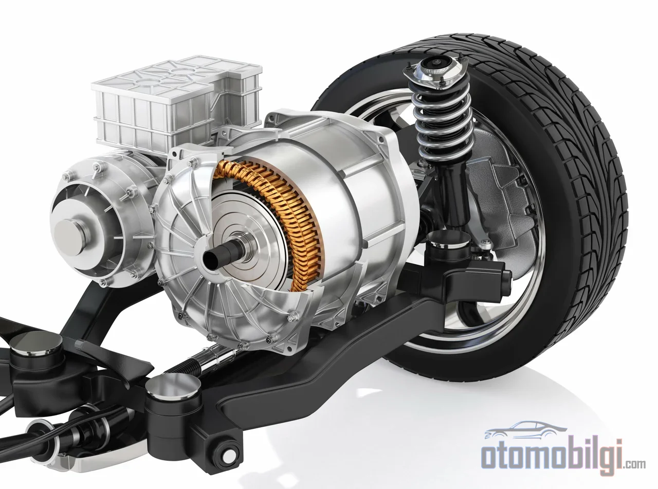
In an electric vehicle, when you press the accelerator from a standstill, we hear that characteristic thin "eee" sound that rises in pitch with speed. Most drivers assume it comes from the motor; in fact, the source of the sound is largely the inverter's switching logic. Converting the battery's fixed DC voltage into a three-phase sine wave with continuously changing amplitude and frequency depends on the micro-decisions made every millisecond by the power electronics at the heart of the vehicle. On this page, we will explain how the inverter actually drives the motor, that is, the effects of PWM modulation, phase current, and switching frequency on torque and efficiency.
First, let's clarify this: the driving feel of an electric car, from millimeter-level throttle sensitivity to instant torque at launch, is largely a product of the inverter software. The motor itself is a magnetic machine; it is the inverter that decides how much current, at what frequency, and in what phase it should be delivered.
What Is PWM: The Road from DC Voltage to a Three-Phase Sine Wave
The battery provides a fixed DC voltage; a permanent magnet synchronous motor or an induction motor, on the other hand, requires a three-phase AC supply with controlled amplitude and frequency. PWM (Pulse Width Modulation) is the bridge between these two worlds. The basic idea is simple: semiconductor switches open and close thousands of times per second, dividing the DC voltage into short segments, and the widths of these pulses are adjusted so that their time average approaches the desired sine shape.
PWM's job is not merely to produce voltage; the real goal is to create a sine-shaped phase current inside the motor that will generate torque. Current flows correctly only when the proper voltage conditions are met, and it is through PWM that the inverter sets exactly these conditions. A three-phase inverter contains a total of eight different voltage vectors; each corresponds to a specific on-off combination of the switches. Motor drive is achieved by selecting these eight vectors sequentially over time.
The Relationship Between Carrier Frequency and Fundamental Frequency
In PWM, two frequencies are mentioned: the fundamental frequency that rotates the motor, and the carrier (switching) frequency that times the switching. The carrier frequency determines how many PWM pulses will be generated per fundamental cycle. As the carrier frequency increases, the synthesized waveform approaches the ideal sine more closely; but there is a cost, because energy is lost at every switching event. Understanding the balance within this voltage-current-time triangle is the key to understanding why an inverter operates at a particular frequency.
Highlights
- PWM enables the motor to generate torque by converting the DC battery voltage into a three-phase sine wave with adjustable amplitude and frequency.
- In EV inverters, the switching frequency is typically in the 5-15 kHz band; this is the reason for the thin tone at launch.
- Compared to SPWM, SVPWM provides higher output and lower harmonic distortion (THD) with the same DC bus voltage.
- A SiC-based EV inverter can show approximately 10% better efficiency than its silicon counterpart.
SPWM and SVPWM: The Difference Between the Two Modulation Strategies
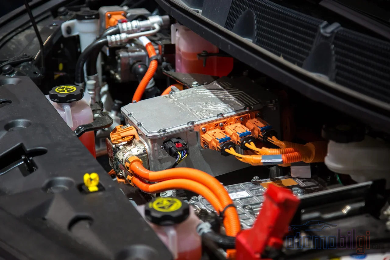
Two fundamental PWM techniques stand out in the literature and in practice: sinusoidal PWM (SPWM) and space vector PWM (SVPWM, i.e. SVM). Both start from the same point: a sinusoidal reference wave. The difference lies in how this reference is processed. SPWM treats each phase independently; it is conceptually simpler. SVPWM, on the other hand, evaluates the three phases together as a single space vector and synthesizes the output through the time-shared use of the eight voltage vectors.
This difference in approach has measurable consequences. SVPWM utilizes the DC bus more effectively; it allows a higher output voltage to be obtained at the same DC voltage level compared to SPWM. Comparison studies consistently show that SVPWM produces a more efficient output with lower total harmonic distortion. Moreover, SVPWM can be designed to operate with a minimum number of switchings; the switching frequency equals the carrier frequency.
| Feature | SPWM | SVPWM |
|---|---|---|
| Processing of the phases | Independent per phase | Three phases together, as a space vector |
| DC bus utilization | Lower | Higher output voltage |
| Harmonic content (THD) | Higher | Lower |
| Conceptual complexity | Simpler | More complex, with an efficiency advantage |
Field-Oriented Control Context
Most modern EV drives operate within a framework called FOC (field-oriented control). FOC is a widely used technique for driving both permanent magnet synchronous motors and asynchronous motors, and it enables the independent, direct control of torque and flux; controlled AC machines thereby acquire a DC-motor-like decoupled torque/flux characteristic. Space vector modulation is one of the standard implementation techniques of this control structure. The torque demand coming from the drive's pedal mapping is converted into current commands by FOC, and into a switching sequence by SVPWM.
Switching Frequency: Balancing Efficiency, Torque Ripple and Sound
The choice of switching frequency is one of the most critical trade-offs in inverter design. On one side there is waveform quality; on the other, losses, electromagnetic interference (EMI) and acoustic behavior. Let us follow, item by item, how this balance is struck.
First, the gains: a higher carrier frequency pushes the switching harmonics further away from the fundamental frequency. The useful output power is produced only by the current at the fundamental frequency; harmonics do not contribute to the motor's work; on the contrary, they cause additional copper losses in the machine. Drives with low harmonic content are therefore more efficient. A high switching frequency also reduces the current ripple; a small-ripple current means small fluctuating forces, and thus less sound and vibration.
Now, the cost side: each switching event produces its own loss, so as frequency rises, switching losses increase and EMI risk grows. Moreover, while a high carrier frequency reduces some low-frequency harmonic effects and the associated motor losses, this does not always mean a cooler-running motor; part of the losses is shifted to the inverter side, to the switches themselves. From the standpoint of practical engineering, the right advice is clear: the switching frequency should be kept at the lowest value that meets the requirements, and raising it should not be seen as an improvement in itself. Techniques such as DPWM also establish a deliberate trade-off between switching losses and current THD.
Why Does the Inverter Sing: The Mechanics of Tonal Noise
The characteristic inverter sound in electric vehicles arises from the switching frequency in the 5-15 kHz band being converted into structural vibration and noise. Conventional EV inverter control uses a fixed switching frequency; and a fixed frequency produces a pure, distinct tone in the spectrum. At startup, when the motor speed (fundamental frequency) is low, this tone is easily audible, and as the vehicle accelerates it blends into the other sounds; the rise in pitch comes from the harmonic components shifting along with the fundamental frequency. Measurements have reported a noise reduction of 25 dB at a 500 Hz switching frequency and 15 dB at 5 kHz; meaning the acoustic outcome of the frequency choice is directly measurable.
Another source of the sound is torque ripple. Periodic disturbing effects such as cogging torque turn into high-frequency speed fluctuations at high speeds, producing acoustic noise and vibration; torque ripple also reduces efficiency. Current studies published in 2026 are focusing on new inverter switching control methods to reduce the high-pitched tonal noise created by a fixed frequency; the goal is no longer just the noise level, but the quality of the sound itself. One of the prominent techniques in this field is Spread Spectrum Modulation (SSM): the switching frequency is deliberately spread within a narrow band, so the pure tone produced by the fixed frequency is distributed across the spectrum and smoothed out.
SiC and GaN: The Semiconductors That Shift the Trade-off Balance
As the switching frequency rises, waveform quality improves, but switching loss and EMI risk grow; in the silicon IGBT world, this equation long suppressed frequency. Wide bandgap semiconductors fundamentally changed this trade-off. Compared to conventional silicon, SiC and GaN devices offer much lower switching losses, higher breakdown voltage, and better thermal conductivity; thus higher frequency became usable together with efficiency and power density values that were previously impossible.
The numbers are striking: An EV inverter using SiC can show approximately 10% better efficiency compared to silicon-based versions. GaN HEMT-based designs have reached 98.5% efficiency in the studied prototypes and have demonstrated superior power density in applications below 650 V. GaN's ability to switch in the MHz range shrinks the size of passive components such as inductors and capacitors; on the motor driver side, this translates into smaller filters, wider torque control bandwidth and lower system weight. As of 2026, the main dividing line in device selection has also become clear: GaN stands out in applications below 650 V, while SiC comes to the fore at higher voltages. Both technologies are being brought together with the efficiency targets of high-switching-frequency three-phase applications in three-level converter architectures.
How Does the Inverter Drive the Motor? Short and Clear Answer
Getting to the heart of the question: the inverter splits the battery's DC voltage into thousands of pulses via PWM, converting it into a three-phase sine wave whose amplitude and frequency are calculated according to the instantaneous torque demand; the sinusoidal phase current shaped by this voltage in the motor windings rotates the magnetic field and produces torque. The switching frequency determines the quality of this process: as it rises, the current becomes cleaner, the torque smoother and the noise lower; in return, switching losses and EMI increase. While SVPWM provides a higher output voltage than the DC bus in this balance, SiC and GaN devices operate with fewer losses at the same frequency, shifting the balance in favor of efficiency.
Conclusion: Silent Driving Is a Software and Semiconductor Decision
The driving character of an electric vehicle is shaped by the inverter's modulation strategy as much as by the motor's power. The same motor produces a different sound, operates at a different efficiency and delivers a different torque feel with a different switching frequency and a different PWM technique. That subtle tone at startup is no longer a flaw, but a sign of engineering balance: the audible face of the compromise struck between frequency, loss, noise and EMI. The agenda for 2026 -sound quality techniques like SSM and switching frequencies expanding their limits with SiC/GaN- shows that this balance is shifting a little more in the driver's favor each year.
Sources
- Power Analysis of PWM Motor Drives - Tektronix
- Space Vector Modulation (SVM) for Motor Control - MathWorks
- Review based on losses, torque ripple, vibration and noise - IET
- New Inverter Switching Control Method to Enhance Sound Quality in EVs - SAE 2026-01-0437
- Field Oriented Control of 3-Phase AC Motors - TI (BPRA073)
- The Truth About Carrier Frequency - Fuji Electric
- GaN and SiC: The Power Electronics Revolution - Microchip USA
- Comparative Review of SiC and GaN Power Devices - AMTI
- Pulse Width Modulation Techniques - Analog Devices
- Vibration and noise characteristics of an inverter for EVs - Extrica