What Is a Resolver? How Does an Electric Motor Know Its Own Position?
Share This Page
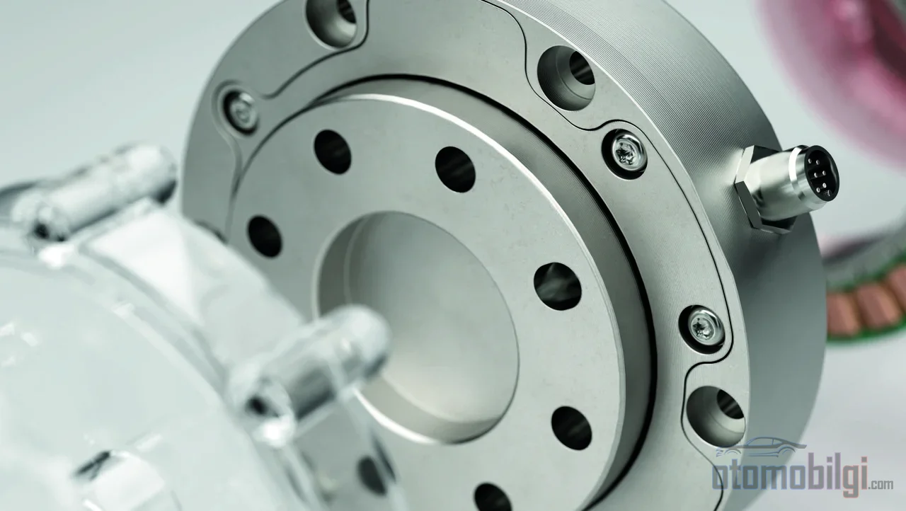
A resolver is an inductive position sensor, operating on the transformer principle, that measures the instantaneous angular position of an electric motor's rotor. The inverter can produce torque by keeping the stator magnetic field 90 degrees ahead of the rotor; for this, it must know where the rotor is, and the resolver provides this data. It does the same job as a Hall sensor or encoder, but its resistance to temperature and vibration makes it the default choice for electric vehicle motors.
Highlights
- A resolver is an analog position sensor that works on the same inductive principle as a transformer.
- Typical excitation frequency 2 kHz or thereabouts; in aerospace applications it goes up to 10 kHz.
- A resolver can operate up to 210 °C; encoders are usually limited to 120 °C . is limited to.
- A two-pole resolver can achieve ±5 arcminutes of angular accuracy.
- Failure symptoms: absence of torque despite pressing the accelerator, speed fluctuation, and abnormal vibration.
What Is a Resolver and How Does It Work?
A resolver is, in essence, a rotating electrical transformer. It is mounted directly on the shaft of an electric motor; the rotor's position within the resolver corresponds exactly to its angular position in the motor. The physics is no different from a household transformer: a high-frequency sinusoidal excitation signal is applied to a primary winding on the stator, and this signal is transferred via inductive coupling to the rotating metal rotor. The critical point is that the inductive coupling between the windings and the machined metal rotor changes according to the rotor's angle.
In the common type - the brushless transmitter resolver - the stator carries three windings: one excitation winding and two windings 90 degrees apart. These two secondary windings induce voltages of different magnitudes depending on the rotor's position; a sine-characteristic feedback signal comes from one and a cosine-characteristic one from the other. By comparing the relative magnitudes of these two signals, the controller calculates the rotor's angle relative to the stator. Over a full turn the waveforms repeat, so the angle information is renewed on every revolution.
Excitation signal and signal processing
The excitation signal is the time reference for the entire signal chain; any distortion in this reference is read directly as a position error. In terrestrial applications 50-60 Hz is preferred, 400 Hz in marine and aerospace, and high frequencies such as 5 kHz in control systems. The power feeding the windings produces no real work, so the voltages are low: below 24 VAC.
Sine and cosine signals cannot be used directly by the controller; resolver-to-digital (R/D) converters are used to convert them into 10-16 bit digital position data. The accuracy side is also data-driven: a two-pole (single-speed) resolver gives absolute angular position within one revolution and achieves angular accuracy of about ±5 arcminutes. Multi-pole designs push this limit - with 16-pole solutions accuracy down to 10 arcseconds is possible, and with 128-pole solutions down to 1 arcsecond.
Why Must the Inverter Know the Rotor Position?
In the permanent magnet synchronous motor of an electric vehicle, torque arises from the interaction between the stator's rotating magnetic field and the rotor's own magnetic field. The goal of efficient commutation is to maintain the 90-degree angle between these two fields. In brushed motors, a mechanical commutator handles this timing; in a brushless motor, no mechanical element takes on this task. The inverter passes the current between the stator phases, and for this purpose it reads the rotor position from a sensor.
This is precisely the core of field-oriented control (FOC): knowing the rotor's electrical angle instantaneously. In PMSM drive, the rotor position (θr) is continuously detected; FOC makes it possible to manage speed and torque smoothly, precisely, and independently of each other. If the timing slips, the cost is immediately visible: if commutation is done too early or too late, the stator field and the rotor position fall out of sync and torque drops. In other words, no matter how advanced the inverter's software is, if the position data it is fed is wrong, the output will be wrong too.
Resolver, Encoder, and Hall Sensor Comparison
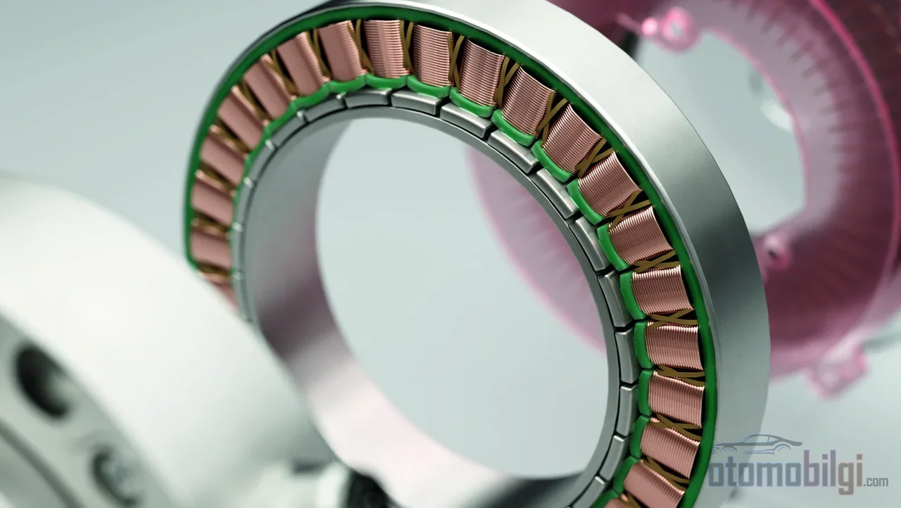
All three sensors do the same job: they convert mechanical rotational motion into an electrical signal to produce position and speed data. The difference lies in the nature of the signal and the durability profile. Encoders produce digital pulse sequences or digital words; resolvers offer an analog sine/cosine inductive connection. Hall sensors provide absolute rotor position but at coarse resolution: they operate in 60 electrical-degree steps and are sufficient for simple control schemes such as six-step drive. Temperature limits are a bonus challenge on top of that.
Thanks to its high resolution, the encoder is the typical choice for precision servo applications; however, it provides relative position. The resolution of optical and magnetic rotary encoders is also limited by disk diameter and line width. In rough summary: an encoder is either durable or cheap, rarely both; the resolver, though it may look expensive, is the one that survives in the harshest environments.
| Feature | Resolver | Encoder | Hall Sensor |
|---|---|---|---|
| Signal type | Analog sine/cosine | Digital pulse/word | Digital |
| Position information | Absolute (within one revolution) | Relative | Absolute |
| Resolution | Very high (increases with pole count) | High, limited by the disk | 60 electrical degrees |
| Temperature tolerance | Up to 210 °C | Up to 120 °C | Limited by temperature |
| Vibration tolerance | Very high | Medium | Medium |
| Additional hardware | Excitation driver + R/D converter | Usually not required | Not required |
The resolver's own weak point
To be fair, the resolver is not perfect either. It requires a separate excitation driver and an R/D converter; moreover, because the sine and cosine outputs are also zero when the excitation voltage is near zero, it is blind for part of each electrical cycle. Tracking R/D converters are used to close this gap - but this can also negatively affect the phase margin.
New-generation solutions are reinterpreting this physical limit. Inductive encoders that use printed circuit boards instead of copper windings apply the same principle as the resolver in a cheaper, lighter, and more compact form. An even more interesting approach is the design that buries the sensing coils inside the motor itself: in this solution, which generates sine/cosine signals from the PWM signal, a resolution of 32,000 counts/revolution, 1.6 counts RMS background noise, and position sampling every 40 µs (25 kHz) across the 0-4,000 rpm range have been measured.
Why Does the EV Environment Choose the Resolver?
Describing the environment a traction motor lives in is easy: temperatures between -40 °C and 150 °C, constant vibration, moisture, oil, and coolant contact. The all-metal resolver is naturally resistant to this profile. When viewed with numbers, the difference becomes clear: the resolver 210 °C can operate at temperature while encoders are typically 120 °C limited to; the resolver can also withstand approximately 5 times higher vibration than the encoder. Therefore the practical selection rule is simple: in every application requiring temperatures above 110 °C, heavy vibration, oil or coolant contact, or long service life, the resolver comes to the fore.
The robustness on the vibration side is no coincidence. Today's traction motor position sensors are designed to process and filter out vibration-induced erroneous signals. In short, an EV manufacturer's preference for the resolver is not an aesthetic choice; it is an engineering necessity imposed by the thermal and mechanical reality of the motor compartment. In safety-critical applications, position feedback must also be absolute and continuous, so the resolver is effectively the default choice.
How Does a Resolver Failure Show Itself While Driving?
A resolver failure directly affects driving even if the motor itself is intact; because the inverter has now closed its eyes to the rotor. Typical symptoms include:
- Incorrect motor speed reading on the display while the vehicle is stationary - a value being shown when the actual speed is zero.
- Inability to get speed output from the motor even though the high voltage is normal and the accelerator is pressed.
- Overcurrent faults and IGBT module failures in three-phase hardware.
- Motor speed fluctuations, stalling, vibration, or abnormal noise.
The most illuminating clue in diagnosis is the speed curve. Motor speed changes smoothly and linearly under normal conditions; a resolver failure produces jagged, notched, and irregular speed curves. It is known that in one case, the abnormal clicking sounds and negative speed readings detected in NVH tests were due to an incorrect resolver wiring harness design - the connection, not the sensor itself, can also be the source of the fault.
Six-wire harness and measurement method
A resolver wiring harness typically contains six wires: ref± (excitation), sin± and cos±. Faults can be detected by measuring the resistance of the three signal pairs at the motor controller or the motor connector. A continuity measurement can be performed by disconnecting the connector; if the resistance is normal but a loose connection is suspected, the harness is wiggled while watching for speed fluctuation on the gauge. After a sensor replacement, a procedure called zero-angle calibration is performed: the angular offset between the resolver's zero position and the motor's zero position is determined. In modern vehicles, model-based diagnostic approaches are also advancing; data-driven and model-based methods aim to identify resolver faults across two typical fault types.
Is a Sensor Truly Indispensable? The Place of Sensorless Control
There really is an alternative: sensorless motor control is a technique that provides closed-loop speed and position control without a physical position sensor. The absence of a mechanical speed sensor in motor drives promises low cost and high reliability; in variable load scenarios it can monitor shaft speed and position. That is why the sensorless versus sensored FOC debate in electric vehicle drive systems is current - some of the proposed approaches aim to be more compact and cost-competitive while offering durability on par with a resolver.
Even so, the resolver's position looks secure. The absolute nature of position information at zero and very low speeds remains the safest foundation for soft starting and precise torque control in a permanent magnet synchronous motor. The evolution of sensorless control is an engineering matter to watch; but today, when you start an electric vehicle's motor, at the end of the shaft there is most likely still this silent, copper-wound transducer turning away.
References
- Resolver (electrical)
- How a Resolver Works | Zettlex | Celera Motion
- Resolver | Function and use in an electric motor
- Rotational Measurements with Resolvers
- EV Motor Resolver Common Faults
- A new option for motor-position feedback: Built-in resolver design
- Feedback Devices: Exploring Hall-Effect Sensors and Resolvers
- Resolvers vs. Encoders: Choosing the Right Sensor for Motion Control
- Resolver vs Encoder Technical Comparison of Position Feedback
- EV Traction Motor Requirements and Speed Sensor Solutions
- Resolvers Vs Encoders for Motion Control
- Sensorless Motor Control: Choosing the Algorithm
- What is Sensorless Closed Loop?