At What RPM Range Does an Electric Motor Operate Most Efficiently?
Share This Page
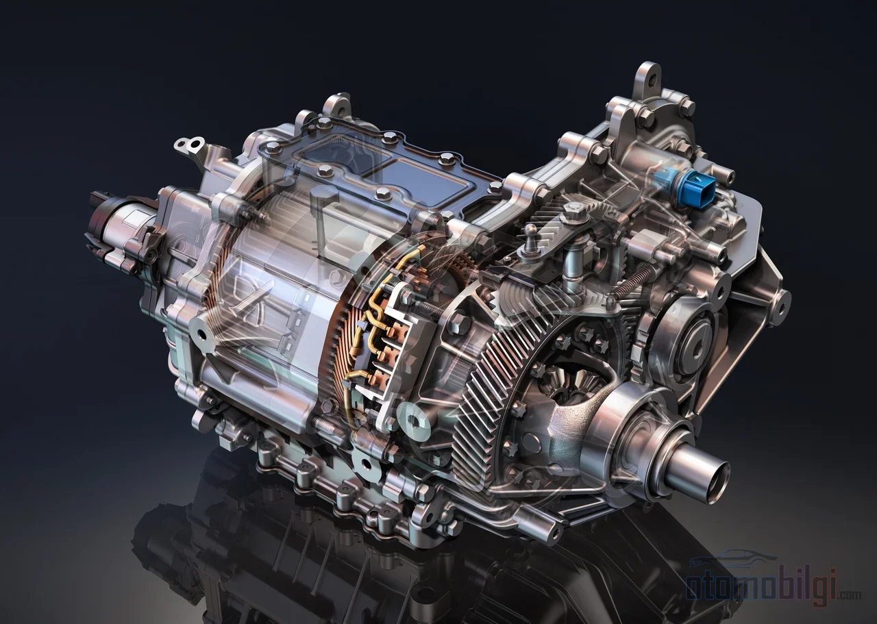
An electric motor reaches its peak efficiency not at a single point, but in a specific region of the torque-speed plane; in most current designs, this region corresponds to the low-to-mid speed and mid torque range. So the short answer to the question is this: the motor runs most efficiently not at full throttle or at a standstill, but in that mid-load band where the vehicle spends most of its daily use. The chart known as the efficiency map shows exactly this region.
Highlights
- An efficiency map is a chart on which efficiency contours are plotted over torque and speed axes.
- In a permanent magnet motor example, the efficient region below 4,000 rpm and below 250 Nm is concentrated.
- The EPA states that EVs use approximately 87-91% of the energy from electricity all the way to the wheels.
- With efficiency map-based torque distribution, up to 8.94% energy savings have been demonstrated in dual-motor vehicles.
- In an inverter example, peak efficiency was 99.57%, and at 5% load, 98.5% was measured.
How to Read an Efficiency Map?
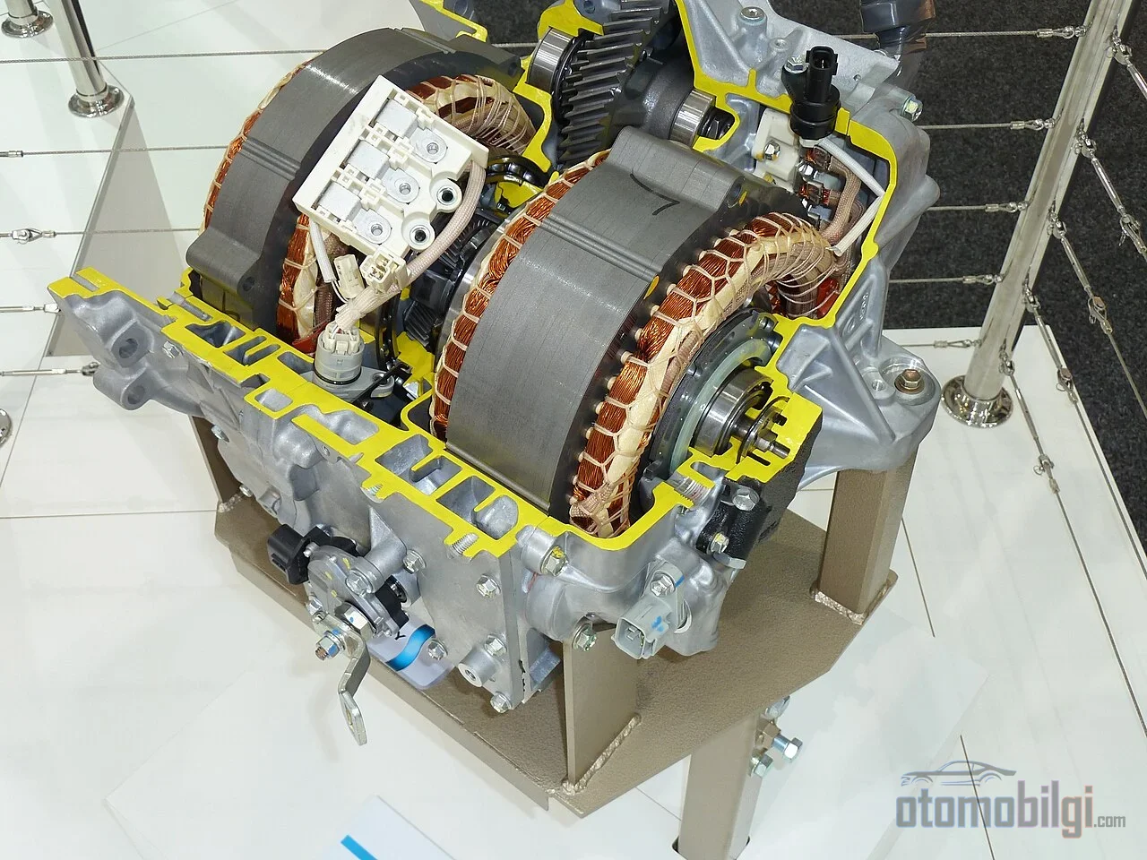
An efficiency map is a chart that shows the motor's entire operating range in a single frame. The horizontal axis shows speed (rpm), the vertical axis shows torque (Nm), and overlaid on it is a contour of the percentage of converting electrical power into mechanical power. These contours, resembling a liquid level map, have an innermost region that is the motor's efficiency island: the more the motor operates within that island, the more of the energy drawn from the battery reaches the wheels.
Let's make the reading concrete. In a published internal permanent magnet (IPM) motor map, the motor operates below 4,000 rpm and at torques below 250 Nm in its most efficient region. This does not mean the motor is weak; it simply indicates that this is where the operating point at which electrical energy converts to mechanical energy with the least loss is located. In the same analysis, a current map and a loss map are also produced alongside the efficiency map; the loss map separately shows Joule losses, iron losses, mechanical and additional losses. When an engineer optimizes the efficiency island, they are essentially squeezing down each of these losses one by one.
To understand the map, two operating regions need to be known. Up to base speed, the motor operates in the constant torque region: it can deliver its peak torque from zero, which is why electric vehicles have such sudden acceleration from a standstill. Above base speed, the constant power region begins; field weakening control comes into play, and torque drops roughly inversely with speed. Since power is the product of torque and speed, the torque curve and the power curve are mirror images of each other.
Where Is the Efficiency Island Located Depending on Motor Type?
Every motor's efficiency map is not the same; the island's location changes directly with motor type. Permanent magnet motors excite their rotors with their own magnets rather than by induction, so they generally offer higher efficiency and torque density; full-load efficiency is higher than asynchronous motors. The price is the cost of the magnets embedded in the rotor. The asynchronous motor's character is exactly the opposite: it maintains its efficiency better at high speed and high torque, but is weak at low speed and low load; its efficiency can drop noticeably at partial load.
| Feature | Permanent magnet (IPM) | Asynchronous |
|---|---|---|
| Efficient region | Low speed, low-to-medium torque | High speed, high torque |
| Low load behavior | Efficiency stays high | Efficiency drops |
| Torque character | Wide and flat constant torque band | Shows slip, starting torque is around 150-200% of rated torque |
| Torque density | High | Lower |
| Cost | High due to rotor magnets | Magnet-free, lower |
The difference between these two maps is not merely a preference but a design space. City-weighted use keeps the vehicle's motor at low speed and low torque most of the time; exactly where the permanent magnet motor's island lies. In high-speed long journeys, the asynchronous motor's efficiency does not collapse as speed increases. Some manufacturers choose the solution of a permanent magnet motor on the main motor on the rear axle and an asynchronous motor on the small front motor precisely for this complementarity: the asynchronous motor provides no free benefit in the low-load conditions where it is inefficient, and engages when needed.
City or Highway: In Which Region Is the Motor Operating?
The relationship between efficiency and speed in an electric vehicle is different from a gasoline vehicle. While an internal combustion engine runs warm and efficient at highway speeds, it delivers poor efficiency in stop-and-go city traffic; in an EV the picture is reversed. Since aerodynamic drag increases dramatically with speed, the electric vehicle's consumption rises on the highway, and in most models the city figure exceeds the highway figure. Real-world range tests confirm this: EVs' real highway range generally falls behind combined official values, because the highway is not the most efficient regime.
The motor itself is the best side of the picture. The EPA's figures show that EVs can use approximately 87-91% of the energy coming from electricity all the way to the wheels; an integrity that cannot even be compared with an internal combustion engine. It is necessary to separate how much of this efficiency comes from the motor and how much from the power electronics. Motor efficiency varies according to operating speed, torque, and control strategy; hardware limits define it, but the field usage is drawn by the control strategy. Field-oriented control (FOC) is the method that decomposes the stator current into torque and flux components and manages both independently, keeping the motor within the efficiency island. The inverter is not the weak link in the chain either: in a 200 kW class design, 99.57% peak efficiency and 98.5% at 5% load have been measured. So the vehicle being efficient in the city is largely the result of the motor's map overlapping with the city regime.
Single Gear and Gear Ratio: Turning the Map into the Real Road
The overwhelming majority of electric vehicles come with a single gear, because the motor can produce torque from zero rpm across a wide speed range; there is no narrow band in which it would need to shift gears. The cost of this is as follows: due to the fixed gear ratio, variable wheel speeds and torque demands push the motor to different points on the map. The choice of gear ratio significantly affects torque delivery and the motor's operating conditions; different ratios change both acceleration and energy consumption. Turning the ratio one way places the urban regime on the efficiency island but pushes highway rpm outside the island; doing the reverse produces the opposite result.
This tension is a current engineering debate. In heavy-duty vehicles, motor efficiency is calculated from the efficiency map for all speed-torque combinations, and since gearbox efficiency also varies with torque, speed, and drive gearing, optimizing the total chain does not end with the motor map alone. As a solution to the single gear's efficiency zone limit, two-speed transmissions combined with traction motor size optimization are being researched; the goal is to ensure the motor spends a larger share of its time on the efficiency island. In heavy vehicles, the gear ratio affects four critical factors in motor behavior at once: torque, speed, efficiency, and load-carrying capacity. In short, the gear ratio is the final adjustment screw that matches the efficiency map to the real-world road profile.
Dual-Motor Architecture: Using Two Maps Together
In a two-motor vehicle, each motor has its own efficiency map, and they do not have to be identical. In the architecture with a main rear motor and a small front motor, total energy consumption varies depending on how torque is split between the two axles. A simple 50/50 split runs both motors at the same point on the map; whereas optimal torque split algorithms distribute driving and braking torque by looking at which motor is in which efficiency zone at any given moment. A distribution where one motor operates at the center of the island and the other at its edge can consume less energy than a symmetric distribution that pushes both motors toward the edge.
In this architecture, where the split is managed electronically through battery power distribution, the gain is not an abstract engineering goal. With a torque distribution strategy based on the efficiency map, energy savings of up to 8.94% have been demonstrated; recovering that much extra from a battery translates directly into range. The same logic works in braking too: which motor produces how much regenerative torque when stopping is chosen according to where the efficiency lies at that moment's speed and torque point.
Regenerative Braking: The Negative Half of the Map
Regenerative braking is the mechanism that runs the motor in reverse to recover the kinetic energy that would otherwise be lost as heat during braking and feed it back into the battery, and it is the invisible second motor of EV energy efficiency. But even when working as a generator, the motor still has an efficiency map; how much of the recovered energy actually reaches the battery depends on which region of the map the motor falls into at the moment of braking. That is why a separate mapping is done for regeneration itself: the energy recovery efficiency is charted under different braking conditions, and the control strategy is tiered accordingly.
The sensitive point here is low speed: at the instant the vehicle has nearly stopped, the energy available for recovery is small, and running regeneration in its inefficient region becomes pointless. Current studies show that the low-speed threshold of loss reduction can be pushed down by up to 5% depending on driving conditions; that is, the system can extend regeneration efficiently down to lower speeds. Multi-stage regenerative control strategies also significantly improve dynamic response. In vehicles with independent motors on all four wheels, map-based energy-saving control distributes braking torque wheel by wheel according to the efficiency map, optimizing driving and braking levels separately. From the user's perspective the result is simple: a well-tuned regeneration means longer range in the same traffic.
What Does the Efficiency Map Mean in Practice?
After reading pages of contour charts, the summary left for the driver comes down to these three sentences. First, the fact that your EV's consumption is low in the city and at moderate speeds is no coincidence; it is the result of where the motor's efficiency island sits in that region, and the rise in highway consumption is the bill of aerodynamics, not the motor. Second, cruise control keeps the vehicle's torque demand smooth on long journeys and protects the motor from being pushed outside the map by sudden high torque demands; smooth demand means staying on the island. Third, in dual-motor vehicles the system constantly compares the two maps without you noticing and tries to assign the work to whichever motor is more efficient at any moment; in regeneration, the same comparison magnifies the recovered energy.
The efficiency map does not have to remain a hidden engineering file for the end user. Knowing at which speed and torque band your vehicle is comfortable lets you put your driving habits on a measurable basis: driving that keeps the motor within its island reduces both consumption and thermal load. Viewed through a mechanical engineer's eyes, the efficiency map is the most honest document that tells an electric vehicle's character in a single frame.
Sources
- Efficiency Maps for Electric Motors Made Easy - Ansys
- Efficiency map - Motor - Altair documentation
- Mastering Torque Curves for Electric Motors
- Electric Vehicle Myths | US EPA
- Real-World Electric Car Range Comparison - Consumer Reports
- How to game efficiency in your electric car - Recurrent Auto
- Efficient Gear Ratio Selection of a Single-Speed Drivetrain - MDPI
- Traction Motor Size Optimization with Two-Speed Transmission - McMaster
- How Many Speed Ratios for Electric Cars? One Example - Gear Technology
- Comparison of torque-split strategies for an independent dual-motor EV - IEEE
- Energy Consumption Optimization of Electric Vehicles - DiVA portal
- Regenerative braking - Wikipedia
- Energy saving control based on motor efficiency map for electric vehicles - SAGE
- Energy Efficiency Improvement Framework for Regenerative Braking - University of Minnesota
- Electric Motor Control: Boosting EV Efficiency - EMobility Engineering
- Induction vs. Permanent Magnet Motors - Horizon Technology
- How a motor's operating speed, torque and control strategy affect its efficiency - Charged EVs