Why Do Electric Motors Lose Power at High RPM?
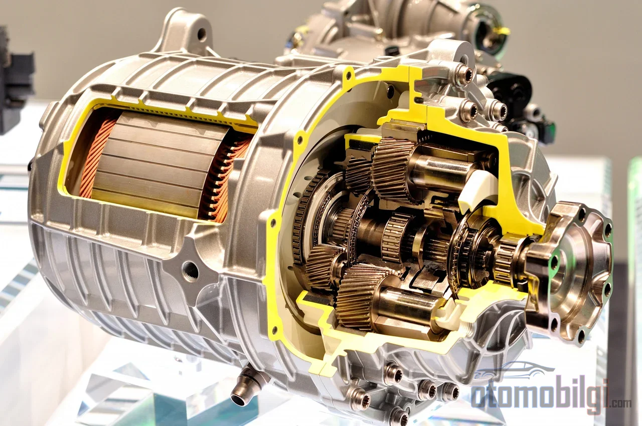
Anyone who looks at the acceleration graph of an electric car encounters the same surprising picture: the motor delivers its full torque at low rpm, the power curve climbs rapidly, and beyond a certain point the torque starts to drop sharply. In an internal combustion engine, gear steps come into play, but an electric motor keeps spinning with a single gear. So why does the same motor, connected to the same battery and with the accelerator fully pressed, produce less and less power at high rpm? The answer is not a fault or a software limit, but pure electromagnetic physics: as the motor spins, it generates a voltage within itself, and when this voltage reaches the limit of what the inverter has at its disposal, the system has to give up torque in order to buy speed. On this page, we explain the mechanism of this trade-off, namely the field weakening region, step by step.
Back EMF: The Enemy the Motor Creates Itself
Every rotating electric motor generates a voltage that opposes the voltage feeding it: the back electromotive force, or back EMF for short. This voltage rises in direct proportion to the rpm and is multiplied by the motor's magnetic flux. At low rpm there is no problem; the inverter converts the battery's DC bus voltage into the phase voltage the motor needs using an appropriate method, and directs the current with ease.
The problem begins the moment the motor reaches its base speed. Base speed is the rpm at which the back EMF reaches the maximum voltage the controller can draw from the DC bus. With linear modulation, the highest phase voltage the inverter can apply to the motor is approximately equal to the DC bus voltage divided by the square root of three; once this point is reached, the inverter is left with no voltage margin to play with between the phases. The voltage applied to force current through the windings must exceed the back EMF; as the margin approaches zero, the controller becomes unable to direct the current, and the increase in speed hits a natural limit.
At this point the controller has two options: either freeze the rpm at base speed, or slow the growth of the back EMF by reducing the flux. The second path is precisely the technique known as field weakening.
How Does Field Weakening Work and Why Does It Reduce Torque?
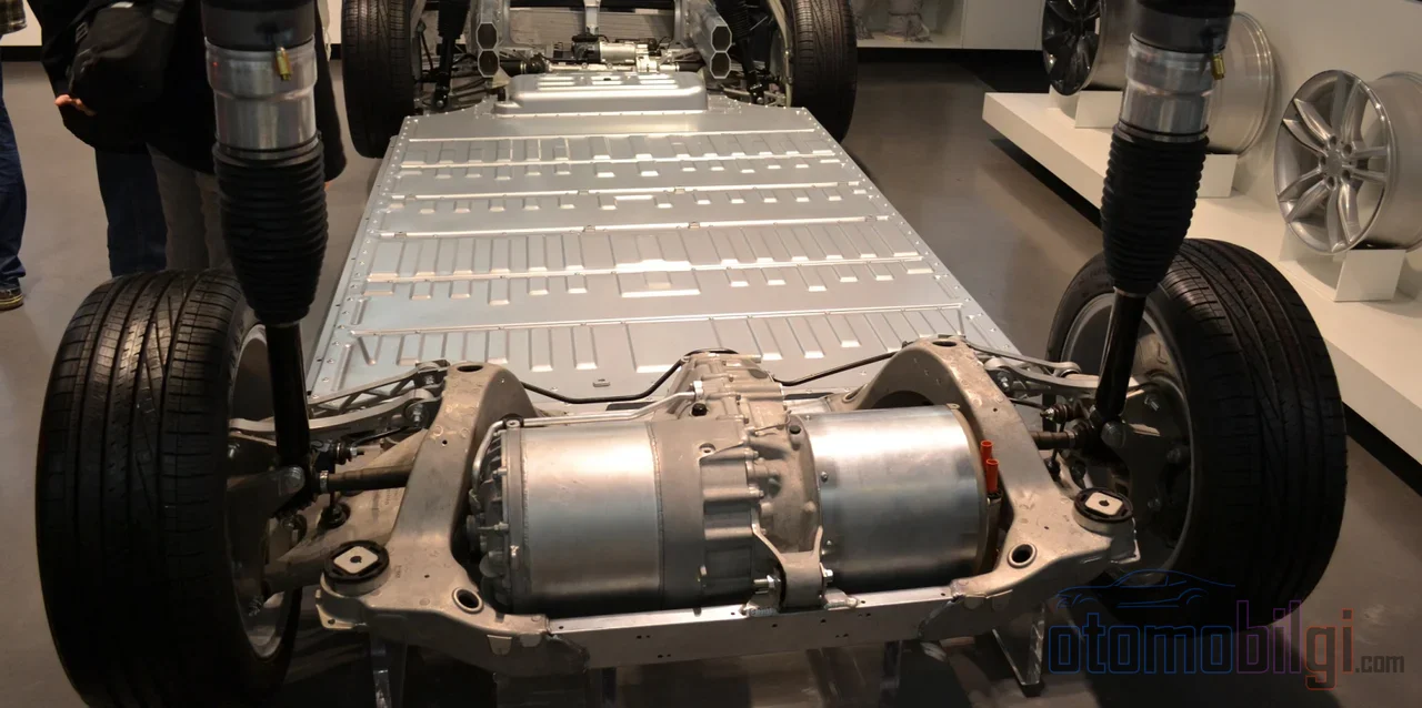
The logic of field weakening is simple: since the back EMF is proportional to both flux and rpm, if you reduce the flux as rpm increases, the voltage stays constant and the motor can spin faster. In permanent magnet synchronous motors, this is done by injecting a negative d-axis current into the windings; this current partially counteracts the rotor's fixed magnet flux and lowers the effective flux.
But the price is inevitable. Torque is the product of flux and the torque-producing current; when you halve the flux, you get half the torque with the same current. Moreover, the stator current is limited by the inverter's current limit, and part of this budget is now spent on suppressing the magnet flux instead of producing torque. In deep field weakening, as the highest rpms are approached, all the current goes to field weakening and the torque approaches zero; even the power collapses in inverse proportion to the square of the speed. This is a deliberate trade-off made by the motor controller between speed and torque, not a loss of capability.
Highlights
- In a typical automotive traction motor, base speed is in the range of 2,500-3,500 rpm, and maximum speed in the range of 10,000-12,000 rpm.
- At highway speeds the motor typically spins around 6,000-8,000 rpm, meaning it is inside the field weakening region.
- From base speed up to maximum speed, motor and inverter efficiency can drop by 5-15 points.
- For passenger electric vehicles, the target constant power speed ratio is approximately 4:1 to 5:1.
How Is the Power Curve Divided into Three Regions?
An electric motor's performance is divided into three characteristic regions on the speed axis, and different laws of physics apply in each one.
- Constant torque region (below base speed): The voltage-to-speed ratio is kept constant, flux remains constant, and the motor produces full torque. Power increases linearly, in direct proportion to speed.
- Constant power region (field weakening): Flux drops roughly inversely proportional to speed, and torque decreases at the same rate; their product, power, remains roughly constant. However, this constancy is not perfect, because losses increase.
- Deep field weakening: As maximum speed is approached, flux and torque fall to very low levels; power too begins to drop, inversely proportional to the square of speed.
Why does efficiency drop above base speed? Because a higher current is required to produce the same torque: increased copper loss, increased switching and conduction loss mean less mechanical power per ampere. For example, in an 80 kW traction motor, base speed is typically in the 2,500-3,500 rpm band, while maximum speed extends to 10,000-12,000 rpm; the efficiency loss between the two points can reach 5-15 points. At highway speeds, in a vehicle with a single-reduction gearbox, the motor typically spins at 6,000-8,000 rpm; meaning highway driving is largely a task performed in the field weakening region.
How Do Motor Types Behave in This Region?
The price of field weakening is not paid equally by every motor type. The three main traction motor technologies separate distinctly in this region.
| Motor type | Field weakening capability | Peak efficiency | High-speed efficiency | Note |
|---|---|---|---|---|
| Permanent magnet (PM) | Limited | 95-97% | Low | Magnet flux is constant and must be overcome |
| Induction | Good | 94-96% | Better | Flux is naturally controlled via slip frequency |
| Wound-rotor synchronous (externally excited) | Excellent | 94-96% | Best | Flux is actively reduced with field current |
The strength of permanent magnet motors is also their weakness: because rotor flux is constant, they offer unmatched torque density at low speed, but at high speed the controller must constantly suppress this constant flux. In an induction motor, flux is induced via slip frequency; when you reduce the magnetizing flux, rotor flux naturally drops, which is why it offers a wider and flatter efficiency map in the constant power region. A wound-rotor synchronous motor, meanwhile, manages rotor flux with a separate field current; the high-speed efficiency is the best of the three because it can actively reduce the field area, while the price is the cost and complexity brought by brush or rotating excitation systems.
IPM vs SPM Distinction
Permanent magnet motors are also divided among themselves. In contrast to the SPM (surface permanent magnet) design, where the magnets are mounted on the rotor surface, the IPM (interior permanent magnet) structure, where the magnets are embedded inside the rotor body, offers a better constant power range and a more controllable field weakening behavior. When a wide speed range is targeted, the design choice mostly favors IPM; on the control side, separately manipulating the d- and q-axis currents through the inverter is the standard way of counteracting the magnet flux. Below base speed, the maximum torque per ampere (MTPA) strategy comes into play, while in deep field weakening the maximum torque per voltage (MTPV) strategy takes over; operating points are determined at the intersection of the voltage limit ellipse and the current limit circle.
What Does This Mean in Real Vehicles?
A few concrete examples clarify how physics translates to the road. The Nissan Leaf EM57 motor operates with a fixed 7.94:1 reduction and enters field weakening above speeds of roughly 56-72 km/h; as it progresses into the deep field weakening region above speeds of 112 km/h, the flux suppression current increases faster than the power going to the wheels for every additional km/h of speed. The induction-motor Tesla Model S has a single 9.73:1 reduction drivetrain; the induction motor's more balanced character in this region, combined with the low drag coefficient body and large battery, makes the highway penalty less noticeable.
Perhaps the most instructive example is the Chevrolet Volt. The Voltec drivetrain has two machines (MG-A and MG-B) operating through a planetary gear set; above speeds of roughly 112 km/h it changes the drive mode, the speed of both motors drops to about half, and thus both motors are pulled out of the deep field weakening region. With this transition, 10-15 percent of the high-speed losses are recovered. Most manufacturers today do not accept this complexity: a single reduction plus a permanent magnet or induction motor is the dominant architecture, and the field weakening loss is paid as the price of simplicity.
Two Sources of High-Speed Range Loss
Only a part of the range loss of electric vehicles at high speed comes from the motor. Aerodynamic drag scales with the cube of speed: for a vehicle with a 0.29 drag coefficient and roughly 2.27 m² frontal area, air drag alone requires approximately 20 kW of power at 105 km/h; the total road load rises to the 23-25 kW band. The motor-related efficiency drop is added on top of this picture. In other words, part of the consumption increase at high speed stems from the physically inevitable drag cube law, and another part from the losses in the field weakening region; confusing the two means misdiagnosing the problem.
Risks and Design Limits
Field weakening is a safe and routine operating mode as long as it stays within the limits of the motor and controller; however, it carries three serious limitations. The first is thermal load: the d-axis current, which produces no torque, heats the windings and power stage as pure copper loss; therefore, cooling capacity and thermal derating come into play. The second is the demagnetization risk in permanent magnet motors: a very strong negative d-axis current, or one applied while the magnets are hot, can cause permanent damage to the magnets; current limits are set according to magnet temperature. The third is voltage surge: if d-axis current control is lost at high RPM, the flux still being produced by the rotor can create a voltage rise exceeding the DC bus value; this is a real failure mode especially in battery systems that are modified by discharging the bus.
Using a wider field weakening range with only controller software, without hardware changes, is often possible; the condition is that the current limit and cooling are sufficient. If the battery voltage cannot be increased, the engineer's alternatives are clear: a motor with a higher nominal RPM or different windings, a higher DC bus voltage (for example an 800V architecture), or a transmission with a different ratio. This framework also explains why the top speed of electric vehicles is relatively low: top speed is defined by the motor's maximum RPM and the back EMF's voltage limit.
Short Answer: Why Is Power Lost?
Electric motors lose power at high RPM because when the back EMF reaches the voltage limit the inverter can supply, the controller is forced to reduce the motor's magnetic flux; the reduced flux produces less torque for the same current, and part of the current budget is spent on suppressing flux instead of producing torque. The result is a drop in torque roughly inversely proportional to speed, and in deep field weakening, the erosion of power as well. This is not a defect; it is the natural price paid by a system that can operate from 0 to maximum speed in a single gear; the designer's job is to strike the balance that minimizes this price between torque density and high-speed efficiency.
Sources
- Field Weakening Explained: When Your Motor Needs It - DMC
- Field-Weakening Control - MATLAB & Simulink
- Field Weakening in VFDs: V/Hz Control and Motor Efficiency
- Electric Vehicle Motor Torque and Power Curves
- Understanding Motor Torque-Speed and Efficiency Curves
- Multi-Physics Comparison of Surface-Mounted and Interior PM Motors - MDPI
- Review of Field Weakening Control Strategies - IEEE
- Hybridisation ratio for hybrid excitation synchronous motors - IET
- EV Design Considerations: Acceleration & Top Speed - Delta Q
- Field Weakening: What, How, and Why to do It