Why Do Inverters Wear Out Electric Motor Bearings?
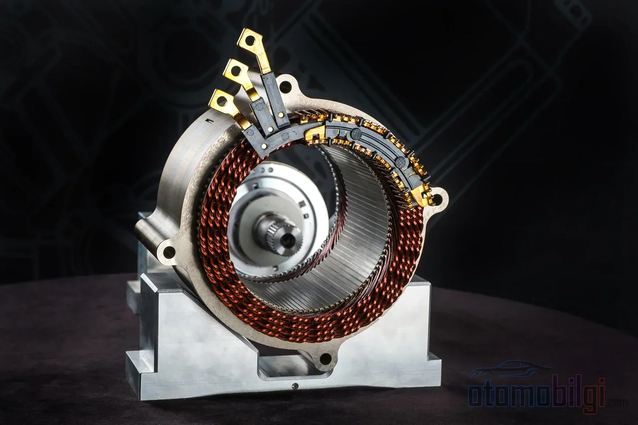
The bearing of an electric motor is designed to carry the load placed on it; the life calculations in manufacturer catalogs are based on load, speed, and lubrication conditions. So how can a bearing end up on your desk noisy, vibrating, and ultimately unusable, without ever experiencing mechanical overload and while the odometer reading is still low? The answer is usually not in mechanics, but in electricity: the shaft voltage that the inverter generates on the motor shaft punctures the oil film and degrades the bearing from the inside, eroding it on a micro scale. This is the least discussed cause of electric car motor failures, and honestly, you can hardly find anything about it in Turkish-language sources.
On this page, we will explain step by step, with numbers, how the inverter wears out the bearing: what common mode voltage is, how electrical breakdown of the oil film occurs, why fluting grooves form, how long it takes for the failure to appear, and what methods engineers use to solve the problem.
Common Mode Voltage: The Side Effect of the Inverter
In electric cars, the current that powers the motor comes from the inverter, which converts the direct current from the battery into three phases. Modern traction inverters use IGBT or SiC switches to turn thousands of volts on and off thousands of times per second. The voltage reaching the motor windings is therefore not a smooth sine wave, but a series of pulses rapidly switching between positive and negative.
This pulsed structure has a price: common mode voltage. In a motor fed by a true sine wave, the average voltage between the three phases is zero at every instant, because the phases balance each other. In a motor fed by PWM pulses, this balance is disturbed and the average voltage deviates from zero; the waveform roughly takes the shape of a square wave or a six-step structure. This unavoidable voltage itself causes a potential to build up on the motor shaft, and here is the critical part: common mode voltage is proportional to the DC bus voltage. In a vehicle with an 800V architecture, higher bus voltage means higher shaft voltage under the same conditions.
Highlights
- A shaft voltage of approximately 6V is enough to puncture the bearing oil film; the range considered normal is 3-5V.
- Electrical bearing damage caused by the inverter typically appears within 1-6 months after commissioning.
- Modern IGBT-based drives produce switching events 20 times faster than the previous generation.
- Bearings are responsible for approximately 60% of electric motor failures.
How Does Shaft Voltage Reach the Bearing?
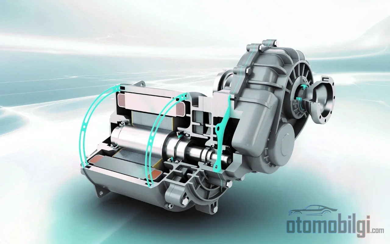
The only point of contact between the motor's rotating shaft and the fixed housing is the bearings. The oil film between the bearing's balls and its raceways is normally thin but a perfect insulator; for this reason, the voltage accumulated on the shaft waits as it builds up until it exceeds a certain threshold. The shaft voltage required to arc across the bearing lubricant is approximately 6V. In operating motors, the 3-5V range is considered normal and does not harm the bearing; by contrast, in motors with developing electrical damage, shaft-to-frame voltage was measured in the 8-19V range, and in some laboratory tests peaks reached up to 70-370V.
When the voltage threshold is exceeded, the oil film is punctured by a miniature spark discharge. This event is identical to the mechanism known as EDM, or electrical discharge machining. The effect of a single pulse seems insignificant; but the microscopic crater it opens creates a discontinuity and attracts subsequent discharges. As millions of pulses accumulate, surface erosion grows rapidly and the bearing quickly reaches a state that requires replacement. The very high switching frequency of modern AC drives is the main reason erosion accumulates this fast.
Three Types of Bearing Current
The ways in which current reaches the bearing are not of a single type. In well-grounded inverter-fed motors, three main destructive types are observed:
- Capacitive discharge current: This is the instantaneous discharge through the oil film of the energy accumulated in the parasitic capacitance between the shaft and the frame; it is the primary source of EDM damage.
- High-frequency circulating current: In large motors, the net asymmetry of the capacitive current leaking from the winding to the stator frame produces a high-frequency magnetic flux circulating around the stator; this flux induces a voltage between the ends of the shaft.
- Shaft grounding current: In installations where grounding conditions are flawed, this is the current that flows through the shaft to the frame and stresses every bearing it finds along its path.
The problem does not remain limited to the motor: through capacitive coupling, the current can also damage the bearings of the gearbox or other equipment connected via the motor's drive coupling. In electric vehicle drivetrains, tribological elements such as bearings and gears are exposed to unwanted leakage currents, and within the motor the bearings are the most sensitive, most vulnerable component to these currents.
Fluting: The Washboard Pattern on the Bearing Surface
The signature of electrical damage is the appearance on the bearing's rolling surface. When a damaged bearing is removed, the balls appear a matte, dull gray; irregular wear on the raceways, discoloration of the grease, and a burnt smell can be observed. The best-known finding is a rhythmic sequence of grooves on the rolling surface resembling a washboard pattern: fluting - in Turkish, "oluklanma" (grooving).
The mechanism forms an understandable chain. Each electrical arc locally heats the oil film and the metal surface at the contact point. Arc heat causes the metal in the damaged region to re-harden; these re-hardened zones become brittle under load and develop cracks. Because the ball follows the same paths on every revolution, the damage is etched into the surface as a periodic pattern. These types of surface damage, classified as frosting, pitting, and fluting in electric motor bearings, directly affect motor performance. Scanning electron microscope analyses clearly show melted and pressed metal particles on damaged surfaces and, in advanced stages, flaking of the shell.
Fluting is not actually a new problem; It has been known and observed since the 1920s. What is new is the switching speeds in inverter-fed motors, which triple the number of discharges.
How Long Does It Take for the Fault to Appear?
The most frustrating aspect of electrical bearing damage is that it is difficult to predict. EDM-type faults produced by high-frequency bearing currents usually appear within 1-6 months after commissioning; the damage can emerge in a week or over several years. The variables that determine the duration are clear: edge speed, switching frequency and bus voltage. High switching frequencies of around 20 kHz create noticeably more bearing problems than settings around 5 kHz; because a higher switching frequency produces more common-mode voltage.
This variability also supports the fact that in electric vehicles the failure profile should be explained by usage rather than mileage. Damage caused by shaft voltage depends on how many hours and under what loads the motor has operated, and with which switching profile; two vehicles may show the same mileage while one has healthy bearings and the other's are full of fluting. The overall picture is still illuminating: bearings are responsible for approximately 60% of motor failures, and a significant portion of bearing failures are electrical in origin. On the other hand, according to a vehicle inspection study in the UK, electric vehicles past 90,000-120,000 miles show about 25% less tendency to fail inspection than petrol vehicles of the same age and mileage; this difference persists beyond 120,000 miles as well. The electric drivetrain remains sound as a whole, but the shaft voltage that pierces the oil film is a silent weak point that can disrupt this picture when the usage profile allows.
Engineering Solutions: Four Ways to Divert Current Away from the Bearing
Since the problem is well understood, the solutions are also mature. All of them rest on a single principle: the path of the discharge current must not pass through the bearing's oil film.
Shaft Grounding Ring
A ring of conductive microfibers wrapped around the shaft, with hundreds of thousands of contact points, directs the current to the housing without ever reaching the bearing, and from there to ground. Unlike conductive brushes, the fibers do not erode the shaft and offer a low-impedance path for high-frequency currents. It also stands out as a cost-effective solution in terms of cost.
Insulated and Ceramic Bearings
To physically break the current path, the bearing's outer ring is coated with an insulating layer or ceramic balls are used. A single insulated bearing used at the non-drive end (usually the end of the shaft not connected to the reduction gear) is often sufficient to stop circulating currents. The ceramic option has two known limitations: the cost is high and in large motors the rotor may still need to be grounded separately; otherwise a risk of arcing arises between the rotor and stator. In other words, a ceramic bearing alone is not a complete solution under all conditions.
Conductive Oil
A more recent approach is to make the oil itself slightly conductive. Oils formulated with fine conductive particles such as graphite or carbon black remove the partial insulating nature of the oil film and prevent voltage from building up on the film; leakage arcing stops, electrical erosion decreases, and bearing life is extended. Field experience is promising: sealed bearings filled with conductive oil have operated in medium-power motors for 5 to 16 years without experiencing electrical damage problems. It should be noted that conventional oils are not conductive, and conductive oil is a separate, deliberate formulation technology.
Reducing at the Source: Winding and Cable Design
The cleanest solution is to prevent the current from forming in the first place. Symagnetic design and tight manufacturing tolerances minimize the asymmetry of the capacitive current leaking from the winding to the housing, and therefore the circulating current. Symmetric motor cables and sine wave filters installed at the inverter output reduce the component of common-mode voltage that reaches the motor; filtering has proven to be a useful escape route in projects where other methods failed. Proper grounding infrastructure is a prerequisite for all of this.
| Solution | Operating principle | Known limitation | |
|---|---|---|---|
| Shaft grounding ring | Directs current to ground via microfibers | Requires installation and shaft surface precision | |
| Insulated / ceramic bearing | Physically breaks the current path | Expensive; rotor grounding may be required in large motors | |
| Conductive oil | Prevents voltage buildup on the film | Requires advanced formulation | |
| Symmetric cable / output filter | Reduces common-mode voltage | Adds extra mass and cost |
Can the Damage Be Diagnosed? Measurement and Imaging
Yes, both live and after disassembly. Vibration analysis and ultrasonic inspection can detect the characteristic fluting pattern while the motor is running; when the damage progresses, the motor begins to produce a distinct noise likened to sawing wood. Discharge level can be measured with a Rogowski coil and oscilloscope; handheld discharge detection pens can identify electrical erosion in bearings without disassembly. After disassembly, surface inspection makes the call: matte gray balls, fluted raceways, and burnt oil confirm the diagnosis.
In summary: The Inverter Bearing Wears Out Electrically, Not Mechanically
The short, quotable answer is this: The inverter, which performs high-frequency switching, generates common-mode voltage in the motor; when this voltage builds up on the shaft and exceeds a threshold of approximately 6V, it electrically punctures the bearing oil film, and millions of microscopic discharges create fluting on the surface, rendering the bearing unusable through electrical erosion far faster than mechanical wear would.
The practical conclusion from the user's perspective is this: this failure follows the usage profile, not mileage, and protection is an engineering decision made at the vehicle's design stage. Which combination is chosen among the shaft grounding ring, insulated bearings, conductive grease, and symmetric winding design determines from the outset whether the motor will run quietly years later or be torn apart inside its grooves. When electric car technology is discussed, battery chemistry and charging speeds take center stage; yet a few volts accumulating on the shaft remains the quietest yet most persistent failure source of the entire system.
Sources
- Electrical Motor Bearing Damage & Shaft Voltage
- Electrically Induced Bearing Damage (EIBD) aka Shaft Currents
- Technical Guide No. 5 - Bearing Currents in Modern AC Drive Systems
- Bearing Current and Shaft Voltage in Electrical Machines
- Experimental Measurement of Shaft Voltage and Bearing Current
- Mitigation Techniques of Shaft Voltage and Bearing Current
- Product Application Note - Shaft Voltages and Bearing Currents
- Measurement and Quantitative Evaluation of Bearing Currents