The Invisible Hand of the Inverter: How Power Electronics Controls the EV?
Share This Page
The inverter in an electric vehicle is the power electronics unit that converts the direct current (DC) from the battery into the alternating current (AC) required for the traction motor to operate; it is also the main control element that regulates the motor's speed and torque thousands of times per second. The battery stores energy, but the layer that turns the wheels and decides how to turn them is the inverter.
Highlights
- Since traction motors run on AC, an electric vehicle cannot be driven without an inverter.
- SiC MOSFETs provide a gain of approximately 3-5% efficiency compared to silicon IGBTs over a typical driving cycle.
- Switching frequencies above 8-16 kHz eliminate audible motor hum, but increase losses.
- In regenerative braking, the inverter works in the reverse direction with the same circuit: it converts AC to DC and charges the battery.
- In an 800V architecture, semiconductors capable of carrying high voltage and current become essential; SiC is the natural answer to this requirement.
What Exactly Does the Inverter Do in an Electric Vehicle?
Its task appears simple at first glance: converting DC to AC. The real work lies in how this conversion is done. The inverter uses a conversion circuit made up of power semiconductor switches; these switches open and close thousands of times per second, transforming the battery's constant direct current into three-phase alternating current at the amplitude and frequency the motor needs. Since traction motors run on AC, this conversion is indispensable.
But the inverter is not merely a converter; it is also the motor's manager. It controls the motor's speed and torque by regulating voltage and frequency; it ensures smooth acceleration and deceleration; and it carries out diagnostic and system protection functions. In other words, the demand from the accelerator pedal reaches the motor through the current waveform adjusted by the inverter. The traction inverter keeps this chain alive by continuously adjusting the motor's torque and speed.
The power class is determined by the motor: electric vehicle traction motors are generally in the range of 30 kW to 400 kW . A vehicle usually has one or two inverters; in in-wheel designs where each wheel uses a separate motor, a separate inverter is required per motor. Single-phase inverters are preferred in small vehicles, while three-phase inverters are preferred in high-performance vehicles; the three-phase structure offers stronger torque control.
What Is Inside the Box?
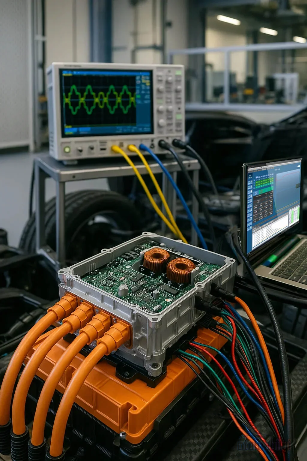
A typical EV inverter consists of several layers: a noise filter, voltage and current measurement circuits, a FET-switched voltage conversion circuit, a control circuit, an auxiliary DC/DC converter, and a CAN or Ethernet-based communication interface. Film capacitors and gate resistors come into play to suppress the electrical noise generated by switching, while the temperature of the switching elements is continuously monitored with an NTC thermistor. This last point cannot be skipped: power inverters generate heat while operating, and as components shrink, heat per unit area increases. High power, heat resistance, and small size are three requirements that must be carried in the same package; the efficiency of the cooling system directly limits the inverter's continuous power.
IGBT or SiC? Comparing the Efficiency Difference with Numbers
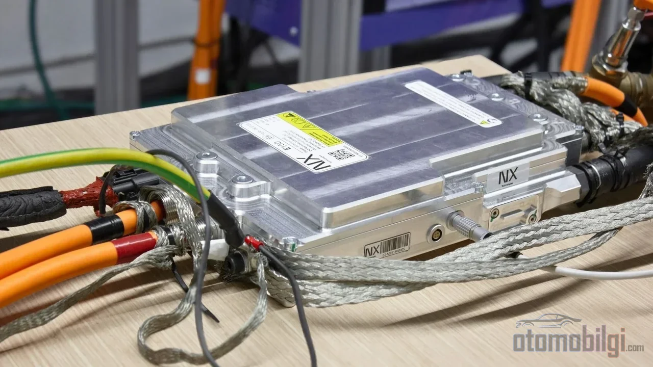
The switching elements at the heart of the inverter were silicon-based IGBTs for many years. In recent years, however, silicon carbide (SiC) MOSFETs are rapidly replacing them in traction inverters, and there is a concrete reason for this: a measurable efficiency difference. In a typical EV driving cycle, SiC produces approximately 3-5% less loss compared to an IGBT. The difference becomes even more pronounced at low load; at low load points representing average EV operating conditions, a SiC inverter has been measured to operate 3.4% more efficiently than an IGBT. In simulations at both 400V and 800V bus levels, a full SiC inverter showed approximately 5% energy savings and a 5% range increase compared to a 600V IGBT.
The device-level advantage is summarized in three headings: SiC reduces both conduction and switching losses thanks to its lower internal resistance. In addition, the PWM dead times in SiC MOSFET inverters - a safety margin left to prevent both switches from conducting simultaneously - can be significantly shortened without taking risks, which once again reduces losses. On the experimental side, the picture is clear: a 30 kW SiC traction inverter has been verified with a peak efficiency of 99.5%. SiC's only weakness is cost; for this reason, hybrid module approaches that combine the two technologies are also being researched.
| Feature | Silicon IGBT | SiC MOSFET |
|---|---|---|
| Driving cycle efficiency gain | Reference | Approximately 3-5% |
| Conduction and switching losses | Higher | Lower (internal resistance advantage) |
| Dead time | Must be kept long | Can be safely shortened |
| Range effect | Reference | Approximately 5% increase |
| Peak inverter efficiency | - | 99.5% (30 kW experimental) |
| Weak point | Losses | Cost |
Behind this difference there is also industrial momentum: forecasts for the SiC traction module market show that the volume of approximately 5.5 billion dollars in 2026 will reach 22.8 billion dollars by 2036, implying annual growth of approximately 15.3%. Movement is fast on the manufacturer side as well; new generation 750V and 1200V class SiC MOSFET families target both 400V and 800V platforms.
Why Does the Switching Frequency Determine the Motor's Sound and Torque?
The inverter's switches operate with PWM - pulse width modulation - and the frequency of this switching directly affects two things the driver notices: the sound the motor makes and the smoothness of the torque. At low switching frequencies, an audible hum, vibration and torque ripple occur in the motor. Carrier frequencies rising above roughly 8-16 kHz render this hum inaudible. Measurements performed on an external-rotor BLDC motor showed that raising the frequency within the 12-28 kHz range reduces acoustic noise but causes the switching elements to heat up.
The engineering decision here is a balance problem. High frequency provides silence and precise torque control, but every switching event means a loss; increasing the frequency erodes the driver's thermal margin. Low frequency, on the other hand, gives cooling room to breathe, but brings back noise and vibration. For this reason, some control strategies aim to reduce perceivability by spreading noise across a wide frequency spectrum instead of concentrating it in a single tone. That fine motor tone - or silence - you hear is actually the sound of a design decision made between efficiency and thermal budget.
How Does the Inverter Work in Reverse During Regenerative Braking?
The most elegant aspect of the inverter is its ability to use the same hardware in the opposite direction. When the accelerator is released or the brakes are applied, the motor changes roles: it starts working like a generator, converting the mechanical energy coming from the wheels into electrical energy. At this point the power flow reverses, and the inverter rectifies AC to DC and feeds the energy back to the battery. In other words, what happens during braking is not an unconventional conversion; it is the same switching circuit operating in a different mode under control signals.
This bidirectionality is one of the fundamental requirements shaping inverter design: the circuit must be able to manage power flow in both directions efficiently. The depth of regenerative braking - that is, how much energy will be recovered - depends largely on the precision of this control. Gasoline vehicles have no inverter in this sense, because they lack a layer requiring an electric traction motor and therefore DC/AC conversion. BEVs, PHEVs, HEVs and FCEVs all use inverters; even in fuel cell vehicles, the battery's DC output must be converted to AC before it reaches the motor.
Why Does Power Electronics Become Critical in the 800V Architecture?
As voltage rises, the same power is carried with less current, which has a direct impact on cables and losses. These are precisely the two main drivers of 800V platform adoption: increased charging speed and reduced cable weight and I²R losses. The industry is moving power architecture from 400V toward the 800V class for high-power applications, and this transition makes semiconductor elements capable of carrying higher voltage and current mandatory. The development of the 750V and 1200V class SiC MOSFET generations to cover both platforms is not in vain: in 800V traction inverters, SiC has established itself as a practically mandatory component.
In such a system, every component becomes even more important. Controlling both conduction and switching losses of the key elements operating at high voltage affects efficiency, thermal management, and fast-charging performance all at once. In an 800V architecture, power electronics stands out not as something beside the motor or battery, but as the critical layer that connects them and defines the system's upper limit.
Summary: The Heart of the Battery-to-Wheel Control Chain
Reading an electric vehicle's performance solely through motor power or battery capacity is an incomplete calculation. Two batteries with the same capacity offer different ranges with two inverters of different efficiency: a 3-5% gain in the driving cycle means measurable kilometers on the real road. The switching frequency determines the sound heard in the cabin, and whether it is SiC or IGBT determines the energy you recover with every charge. The inverter is the silent but decisive link in this chain - a component that goes unnoticed not because it is unseen, but because it does its job well.
Sources
- What Is an Inverter in an Electric Vehicle? - Panasonic Industry
- How a Vehicle Inverter Works - A&D Technology
- EV Inverters: How They Work & Their Role in Electric Vehicles - Ennovi
- SiC Replacing IGBT in EV Traction Inverters - PatSnap
- How SiC Can Boost Efficiency and Reduce Costs in Power Electronics - PSMA
- SiC vs IGBT: EV Inverter Technology Compared - nx-tech
- Performance Comparison of Si IGBT and SiC MOSFET - MDPI
- High efficiency SiC traction inverter for electric vehicles - IEEE
- PWM Dead Times in Automotive Traction Inverters - IET Power Electronics
- The Truth About Carrier Frequency: Noise, Heating, and Motor Stress - Fuji Electric
- VFD Switching Frequency - KEB America
- Analysis of the Effect of Switching Frequency on Acoustic Noise in External Rotor BLDC Motors - ResearchGate
- SiC Power for 800V EV Traction Inverter Platforms - Wolfspeed
- STMicroelectronics unveils new generation of silicon carbide MOSFETs - ST Newsroom
- How 800V EV Innovations are Redefining AI Data Centers - IDTechEx
- The importance of inverter cooling for electric vehicles - Eaton
- A closer look at regenerative braking - Charged EVs
- SiC Traction Modules Market - Fact.MR