What Does a DC-DC Converter Do in an Electric Car?
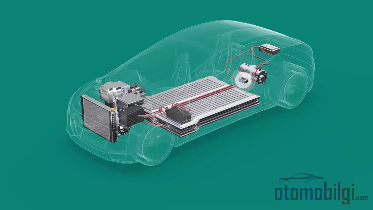
Under the hood of an electric car - which in most models is actually a trunk lid or a front trunk - an energy source of hundreds of volts has to live alongside a handful of 12-volt consumers. Headlights, instrument panel, infotainment screen, window motors, door locks: all of them are inhabitants of the 12-volt world, oblivious to the high-voltage battery's magic. There is a single component that builds the bridge between these two worlds; when a failure tears down that bridge, the vehicle cannot wake up even if the 800-volt battery is full. That component is the DC-DC converter.
What does a DC-DC converter do in an electric car?
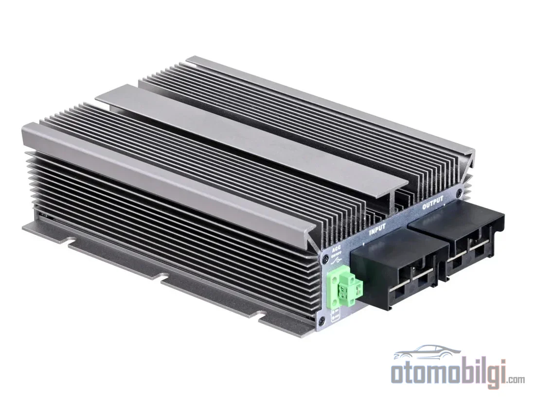
The answer, in one sentence: it steps down the few hundred volts of direct current from the core battery to the 12 volts (or 48 volts on some platforms) required by the auxiliary electrical system. But that sentence is the easy part. The real issue lies here: in an internal combustion vehicle, the alternator that feeds the 12-volt system draws its power directly from the engine's rotation. An electric vehicle has no engine - or rather, its spinning electric motor does not offer a belt pulley the alternator could use without interference. So the electric vehicle was designed as the first alternator-free car in history, and filling that gap required a completely different solution.
That solution: an alternator in solid state. The main traction battery typically produces 400-800 V; the converter chops and transforms this voltage and takes on two separate jobs. First, it directly feeds the low-voltage consumers while the vehicle is running - the current does not need to pass through the 12 V battery. Second, it keeps the 12 V battery topped up by charging it continuously with small currents. So the battery is a buffer; the actual supply path is the converter itself. This architectural difference also dictates the failure symptoms to us: when the converter dies, the vehicle's problem is actually not in the 12 V battery but in the source that charges it.
Highlights
- The main battery produces 400-800 V; the auxiliary systems run on 12-48 V, and the bridge between them is built by the DC-DC converter.
- Modern converters with an LLC resonant topology operate at hundreds of thousands of switching events per second with over 90% efficiency.
- Commercial solutions range from 0.6-6 kW; high-power units can deliver output currents of up to 280 A.
- When the converter fails completely, the vehicle cannot enter READY mode despite a full battery and cannot even be charged.
Stepping 400 volts down to 12 volts: the four stages of the conversion
If it were possible to reduce voltage with a simple resistor, engineers would have chosen a different career instead of reading this article. Voltage dropped across a resistor is wasted as heat, and every watt counts in an electric vehicle. That is why the converter uses a switching conversion chain that minimizes losses, and the chain can be summarized in four stages: the DC is converted to high-frequency AC; the voltage is stepped down with a transformer; the output is rectified back to DC.
Anatomy of the circuit
- Input EMI filter: It filters out ripple and electromagnetic interference on the high-voltage line; ensures that the radio and sensors are not affected by the converter's switching.
- Power switching stage: In a half-bridge or full-bridge arrangement, MOSFETs and IGBTs turn the DC input into a high-frequency square wave on the order of kHz.
- High-frequency transformer: Provides galvanic isolation between the high-voltage and low-voltage sides - the two sides do not electrically touch each other. The turns ratio performs the step-down exactly at this stage.
- Output rectifier and LC filter: Diodes, or MOSFETs in synchronous rectification, convert AC to DC; the LC filter produces a stable, ripple-free 12 V output. Synchronous rectification significantly reduces conduction losses.
Why is the frequency chosen so high? Because the size of the transformer shrinks as the operating frequency increases. While a 50 Hz grid transformer weighs as much as a brick, an automotive transformer operating at hundreds of thousands of switchings fits in the palm of a hand. Most modern electric vehicles use an isolated LLC resonant topology: the resonant circuit ensures that the switching MOSFETs are turned off at the moment the voltage across them reaches zero (ZVS), effectively eliminating switching losses. This is the engineering behind the over 90% efficiency figure.
The final layer is intelligent control. The converter's control unit continuously monitors the output voltage and regulates it in a closed loop: at night the headlights turn on, the AC compressor kicks in, the load suddenly increases - the controller raises the PWM duty cycle and the output remains steady at 12 V. As long as the vehicle is running, the converter is on duty without interruption; in extremely hot or cold conditions, with heating and cooling consumers loaded at the same time, it experiences the most demanding moments of its life.
How powerful should it be? The logic of sizing
The first question in converter selection is the power class: the unit's maximum output capacity must be able to meet the total needs of all low-voltage loads connected to the vehicle. For this, engineers draw up a power list of the connected loads and evaluate the input/output voltage ranges, efficiency curves, and cooling capacity together. Commercial solutions range from 0.6 kW to 6 kW; cooling can be natural, air, or water-cooled. A common mid-range value is the 2.2 kW level, delivering approximately 160 A at 13.8 V.
| Parameter | Main converter | Backup power version |
|---|---|---|
| Input voltage (800 V variant) | 420-880 V | 380-960 V |
| Output voltage | 8-14 V | 9-16 V (nominal 13.3 V) |
| Output current | Up to 280 A | Up to 22 A |
| Efficiency | Up to 94% | - |
| Cooling | Active | Passive |
| Operating temperature | -40 °C to +85 °C | |
The second column in the table shows a little-known architectural detail: some manufacturers place a low-power backup converter alongside the main converter. This unit, with 150-350 W, powers the vehicle's critical systems in standby mode and operates with passive cooling. The main unit is volumetric, actively cooled, and certified up to ASIL-D level according to the ISO 26262 standard in terms of functional safety; It communicates with the vehicle's control systems via the CAN bus. The failure of a converter no longer just means dark headlights; it means a safety-related software layer.
The life of the 12 V battery in a vehicle without an alternator
The 12 V battery still exists in an electric vehicle, and it is still critical. The instrument panel, lighting, controllers, window motors, locking - all of these operate in the low-voltage domain. The high-voltage line cannot directly power these systems; even closing the contactors depends on the 12 V side being alive first. The most striking consequence here is this: When the 12 V battery is dead, the vehicle cannot even be charged. The contactors that connect the high-voltage system to the grid cannot close without the command chain being powered from the low-voltage side.
The battery is supported through a process called trickle charging: the converter sends small, regular currents to the battery, keeping it always full. The target voltage range is the 13.5-14 V band favored by classic lead-acid or lithium batteries; even when the battery is empty, the converter tries to maintain this band. In other words, in a well-designed system, the 12 V battery is almost never strained - because the real load rests on the converter's shoulders.
Failure symptoms: what happens when the bridge collapses?
When the converter fails, the picture resembles an ordinary 12 V battery problem but is more stubborn. The battery does not charge; the vehicle cannot enter READY mode; low-voltage faults repeat. In the event of a complete failure, random warning lights come on, the vehicle refuses to start, refuses to accept a charge, or repeatedly drains the 12 V battery. Even if the high-voltage battery is flawless, the vehicle cannot wake up because it cannot close the contactors. On some platforms, partial failure manifests itself as a sudden loss of power to the control systems during driving - which is the most dangerous scenario.
The face of low-voltage collapse
- Headlights dimming noticeably, especially in idle-like situations.
- Screens flickering and dimming; instrument displays restarting.
- Electric power steering behaving erratically, heavily, or abruptly.
- Vehicle-wide warning lights, electrical noise, and total system blackout.
The origins of the failure can be varied: problems in the unit's internal structure, cable and connector issues, overload, or degradation of insulation over time. Diagnosis is just as systematic as the operating principle: the technician first measures the input and output voltage, then looks at ripple characteristics and efficiency under various loads. When the switching waveform is shown on an oscilloscope screen, the failure mechanism often reveals itself. The subtle distinction is here: failures on the 12 V side announce themselves with starting failures and flickering lights; failures on the high-voltage side, on the other hand, strike at range and charging.
Topologies, lifespan, and cost
The step-down buck converter is the most common solution in electric vehicles, with efficiency typically in the 90–95% range. Step-up boost converters are mostly found in mild hybrids, used to generate 48 V from 12 V. Bidirectional converters, on the other hand, allow energy flow in both directions: the path of energy recovered through regenerative braking, and the foundation of vehicle-to-grid (V2G) applications. In modern automotive converters, overall efficiency typically ranges from 85–98%; silicon carbide semiconductors are pushing efficiency and power density even higher.
The question of lifespan and cost matters in practice. A quality converter typically lasts 10–15 years under normal conditions; lifespan depends on temperature, load profile, and component quality. The replacement price is around $100–300 for simple units, and up to $1,000–3,000 for high-power bidirectional units. One final distinction clears up the confusion: the onboard charger (OBC) converts AC power from the grid into DC to charge the main battery; the DC-DC converter, meanwhile, manages voltage conversion between the vehicle's own DC systems. The DC-DC converter does not charge the high-voltage battery - the jobs of the two components never overlap.
Conclusion: small box, big dependency
The DC-DC converter is one of the least discussed but most critical components of an electric car. It safely steps down the energy of the 400–800-volt traction battery to 12 volts using high-frequency switching and galvanic isolation; in an architecture without an alternator, it is the only real power source of the low-voltage world. When it fails, the entire battery is useless: contactors do not close, the vehicle does not wake up, charging does not begin. In many ways, the true heartbeat of an electric vehicle comes from this silent box's hundreds of thousands of switchings per second.
Sources
- DC-DC Converter in EVs: Role, Architecture, and Operating Principles - Brogen EV Solution
- How a DC DC Converter Works in Electric Vehicles - Daygreen
- DC DC converter for optimal voltage conversion - Preh GmbH
- Automotive - Electric Vehicle Main DC-DC Converter - Skyworks
- A closer look at DC-DC converters - Charged EVs
- 12-Volt Batteries On Electric Cars: Everything You Need To Know - InsideEVs
- Why Do Fully Electric Vehicles Still Have a 12V Battery in Them? - Midtronics
- Signs of a Failing DC-DC Converter in an Electric Car - Autodoc
- EV DC-DC Converter Explained | 12V Faults, Symptoms - EV Repair Specialist
- Power Electronics Converters for Electric Vehicle Auxiliaries - MDPI