What Does the Pre-Charge Circuit Do in an Electric Car?
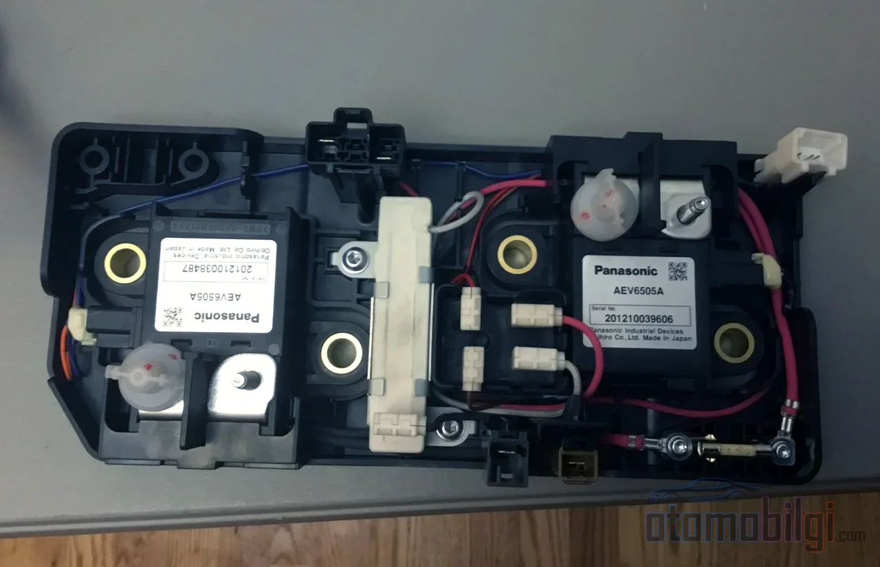
The moment you switch on an electric car, most of the time between getting in through the driver's door and the READY light coming on passes with an electrical ritual that most drivers never notice: pre-charge, that is, the pre-charging stage. This stage lasts a few hundred milliseconds, and during this time the vehicle connects the high-voltage battery to the traction inverter gradually and in a controlled manner, rather than "brute-forcing" the connection. Suppose you were to skip this stage: the moment the contactors close, an empty DC-link capacitor acts like an effective short circuit, and currents of thousands of amperes can damage the cables, connectors, fuses, and the inverter itself. The pre-charge circuit steps in exactly at this point.
This is not about battery chemistry; it is about power electronics and system architecture. On the high-voltage side of an EV, this chain, extending from contactors to capacitors and resistors, sits at the center of the vehicle's operating logic and safety philosophy. Let us look at it with numbers and a chain of logic.
The DC-Link Capacitor and the Inrush Current Problem
There is a buffer stage between the high-voltage battery and the traction inverter: the DC-link capacitor. This capacitor, whose capacitance typically ranges from a few hundred microfarads to a few thousand microfarads, has two basic functions. First, to separate the parasitic inductance effects between the battery and the load from each other; second, to provide a low-impedance path for the high-frequency current at the inverter's switching frequency.
The problem is this: when the vehicle is off, there is no voltage in this capacitor. The main contactors, commonly designated in vehicles as MCP on the positive side and MCN on the negative side, are in the open position, and the battery is separated from the load at both terminals. The moment the contactors close, however, the empty capacitor appears to the battery as a direct short circuit. The result, if not limited, is a very high inrush current, that is, a capacitive inrush current. This current can damage the cables, connectors, and fuses.
Highlights
- Pre-charge is a stage designed to charge the DC-link capacitor through a resistor before the main contactors close.
- In 800V systems, the typical target is a pre-charge time of around 150ms with an upper limit not exceeding 400ms.
- If pre-charge is not performed until the capacitor reaches 90% of the battery voltage, contactor life is dramatically shortened.
- The most common symptom of pre-charge failure: the READY light does not come on, and the vehicle cannot enter drive mode.
How Does the Pre-Charge Circuit Work?

In the traditional design, two additional components are sufficient: a pre-charge contactor (PCC) and a current-limiting resistor. The logic is simple. In the pre-charge phase, the PCC and the negative main contactor close; the main positive contactor is still open. Thus, the battery current flows through the limiting resistor to the capacitor, and the voltage approaches the battery voltage following an exponential curve. When the capacitor is sufficiently charged, the PCC opens, the main positive contactor closes, and the resistor is removed from the circuit. Current now flows directly from the main contactors to the inverter, without heat loss in the resistor.
Contactor Closing Sequence
A typical power-up sequence consists of four steps, and the order of the steps is critical for safety:
- After the power-up command, the main negative contactor is closed.
- The pre-charge contactor is closed; the capacitor begins charging through the resistor.
- The main positive contactor is not closed until the DC-link capacitor voltage reaches 90-95% of the battery voltage.
- After the main positive contactor is fully closed, the pre-charge contactor is opened.
The battery management system (BMS) evaluates the completion criterion of the pre-charge. When the difference between the capacitor voltage and the battery voltage falls below a certain threshold, commonly 50V or about 10% of the battery voltage in practice, the stage is considered complete and the main contactor is allowed to close.
Pre-Charge Design in Numbers
A concrete calculation, rather than an abstract description, clarifies the logic of the design. Let us take an 800V battery, a 1000µF DC-link capacitance, and a pre-charge time target of 150ms. The capacitor's charging curve depends on the RC time constant; in practice, the pre-charge time is taken to be approximately three time constants (3τ). To meet this target, the resistor must be chosen below 50Ω. With this value, the peak current is 16A according to the V/R relation, and the instantaneous average power of the resistor is approximately 1925W. The resistor needs to carry this power not continuously, but only for a short pulse; however, repeated switching cycles pave the way for heat-related failures. In design practice, the pre-charge time of the DC-link capacitor is expected not to exceed 400ms. As the system voltage and capacitance grow, this time lengthens and can reach several seconds in large systems.
Due to the nature of exponential charging, the capacitor voltage reaches approximately 95% of the battery voltage at three time constants; the remaining difference shrinks progressively. Therefore, pre-charge waits not for "fully charged" but for "sufficiently charged"; what is critical is that the remaining difference produces a reasonable current when the main contactor closes.
Contactor Welding: What Happens Without Pre-Charge?
The purpose of the pre-charge circuit is not only to limit the inrush current, but also to protect the contactor's lifespan. The higher the current the main contactors face when they close, the greater the risk of the contact plates inside them fusing and welding together. The most common causes of welding are capacitive inrush currents, short-circuit currents reaching thousands of amperes, and accumulated arc energy.
The consequences of a welded contactor are serious: since the contact plates are permanently joined, the vehicle cannot interrupt the high voltage. This means the safety chain is broken at the moment of a failure. Connecting a sudden capacitive load without pre-charge can cause the main contactors to weld instantly.
The Relationship Between Pre-Charge Percentage and Contactor Lifespan
Industrial data demonstrates this relationship strikingly: a high-voltage contactor is rated to withstand 50,000 closing operations when pre-charged to 90% of the DC-link battery voltage, while at an 80% pre-charge level it withstands only 50 closing operations. In other words, a ten-point pre-charge deficit shortens contactor life a thousandfold. A stage lasting a few hundred milliseconds that the driver never sees is actually one of the most critical parameters determining the system's durability.
How Does a Pre-Charge Failure Manifest to the Driver?
When the pre-charge circuit fails, the vehicle usually silently refuses to start. The logic chain is simple: the BMS waits for pre-charge to complete; if the resistor or pre-charge contactor is faulty, the capacitor voltage does not rise, the completion criterion is never met, and the BMS does not authorize closing the main contactors. Without the main contactors closing, the vehicle cannot enter drive mode either.
The symptoms are familiar: the READY light on the instrument panel does not illuminate, the vehicle does not shift into Drive or Reverse, and a pre-charge-related error is displayed on the screen. The failure may also manifest as the vehicle stopping driving or charging for protective reasons. In real-world examples, in an electric vehicle with a failed pre-charge resistor, even with the 12V battery fully charged, the vehicle would not enter drive mode, and systems such as heating and defrosting also did not work. Possible root causes include capacitor failure, contactor failure, and delay timer failure. In some systems, the BMS also waits for pre-charge to finish and enters a fault state if the expected time is exceeded.
Resistor or Active Electronics? The Design Debate
The traditional pre-charge circuit consists of electromechanical relays and a high-power resistor; this is a structure that conflicts with expectations of high power density and low component cost. Multiple approaches are being discussed in the industry to ease this tension. Alternatives include active pre-charge controllers, discrete high-voltage buck converter designs, software-based integrated solutions, and a bidirectional HV-LV DC-DC converter architecture. Among these options, the traditional resistive design has the lowest power density and the highest component cost; the bidirectional DC-DC approach, meanwhile, offers the highest power density.
Solid-state relay (SSR) based solutions promise increased reliability, less weight, smaller size, and response times below 3µs compared to mechanical relays; the response time of mechanical relays falls in the 1-50ms range. The large capacitive loads in 800V traction inverters continue to require dedicated pre-charge circuits to avoid damaging inrush currents.
The counterargument is also strong: the pre-charge resistor is a passive component with high architectural independence. It works in 400V and 800V architectures and even in architectures completely free of the 12V system; it carries no dependency on complex electronics or software. As the number of active components increases, the probability of failure also increases. Additionally, if the goal is to eliminate the 12V battery from vehicles in the future, a DC-DC based pre-charge solution will require redesign. There are also approaches that aim to eliminate the pre-charge circuit entirely using a power module approach; however, the industry has not yet converged on a single point in this balance between simplicity and integration.
In summary: What Does the Pre-Charge Circuit Do?
The short, quotable answer is this: The pre-charge circuit limits the inrush current by ensuring that, in an electric car, the DC-link capacitor charges in a controlled manner through a resistor before the main contactors close; thereby preventing contactor welding and damage to power electronics components. It is invisible to the driver, yet it is in operation every time the vehicle is started as the first condition of safety and component lifespan.
The next time you switch on your electric car, wait for the READY light to come on within a fraction of a second: in that brief silence, a resistor is absorbing thousands of watts for a few hundred milliseconds, a contactor is waiting for the safe moment, and the BMS is monitoring the voltage difference. This overlooked stage is the smallest yet most decisive link in the safety architecture of modern electric vehicles.
Sources
- DC-Link Capacitor Pre-Charge Designs in Automotive Systems
- Precharge resistor vs. DC-DC converter in electric cars
- Power Modules Eliminate EV High-Voltage Pre-Charge Circuitry
- Sensata Precharge Circuit Whitepaper
- DC Precharge Circuit for Hybrid and Electric Vehicles
- What Is a Precharge Circuit & How to Size It for Battery