How Does a Constant Velocity Joint Transmit Power Without Loss?
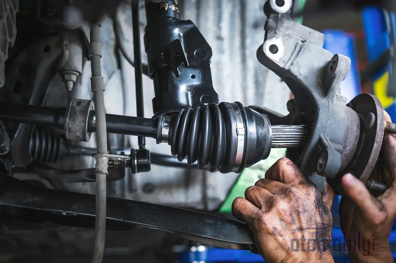
When you turn the steering wheel to full lock in a corner, the front wheels turn at an angle approaching 45 degrees, the suspension moves up and down with the bumps at the same time - and the torque coming from the gearbox reaches the wheel without interruption despite all this changing geometry. The component that takes on this job is the constant-velocity joint, one of the most invisible yet most critical components of the drivetrain. So how can the output speed remain equal to the input speed while the angle between the two shafts constantly changes? The answer lies hidden in the geometry of a few steel balls and a cage that guides them.
What Is a Constant-Velocity Joint and What Does It Do?
A constant-velocity joint - known in English literature as a constant-velocity joint, or CV joint for short - is a machine element that establishes a mechanical connection between two rotating shafts positioned at an angle to each other and ensures that both shafts rotate at the same speed regardless of that angle. Its purpose goes far beyond abstract definitions; it is based on a concrete engineering requirement: to carry the torque coming from the gearbox and differential to the wheels along a path that does not proceed in a straight line.
Let us follow the power flow in order: engine, clutch, gearbox, differential, axle shafts, constant-velocity joints, and finally the wheels. Every link in the chain operates on an almost fixed axis; and not only the last link. When you enter a corner, the wheel changes direction; when you hit a bump, the suspension compresses and extends. The connecting element in between must absorb both of these movements, and on top of that must transmit the torque without any loss. The constant-velocity joint delivers balanced torque transmission at every operating angle without a noticeable increase in friction or the formation of backlash.
Why Isn't a Conventional Universal Joint Enough?
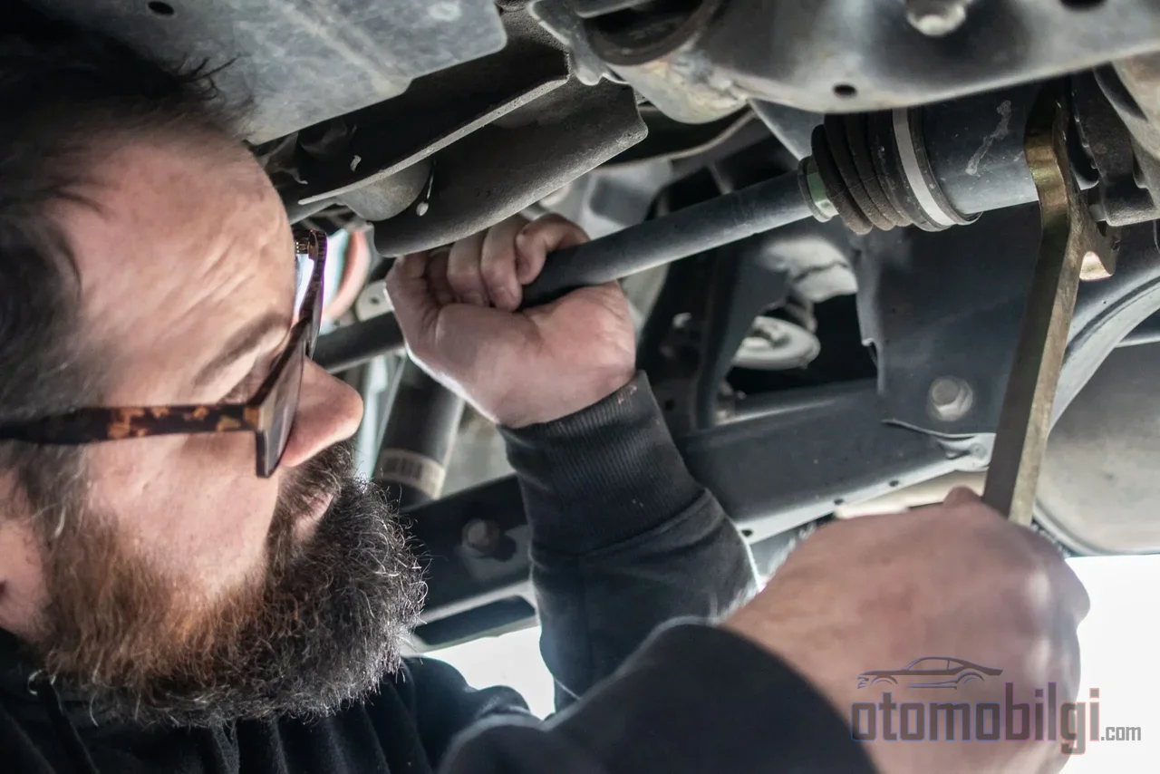
The root of the problem dates back to the 16th century. The universal (Cardan) joint developed by Gerolamo Cardano can transmit rotational motion between angled shafts - but with one flaw: while the input shaft rotates at constant speed, the speed of the output shaft fluctuates. This speed variation grows as the angle between the shafts increases and is felt as vibration in the driver's steering wheel and seat. As the angle increases, the connection also gives an intermittent feel.
On front axles this is unacceptable. Steering angles easily exceed 40 degrees; at these angles, the speed fluctuation of the Cardan joint is enough to swing the car and strain the drivetrain. In the 17th century, Robert Hooke developed the double Cardan solution, in which speed variations cancel each other out, by connecting two universal joints offset by 90 degrees in series - this is considered the first constant-velocity joint type. The real breakthrough came in 1926 with Alfred H. Rzeppa's six-ball joint design; the design was patented in the USA in 1927 (patent no. 1,665,280). In 1931, the DKW F1 took to the road as a front-wheel-drive vehicle, and in 1958, with Alec Issigonis's Mini, the front-wheel-drive layout with constant-velocity joints became widespread.
Highlights
- Rzeppa-type outer joints typically allow 45°–48° of articulation, and some modern designs 54° (NTN, 2007).
- The inner tripod joint operates with axial slip (plunge) of up to 50 mm and an angle capacity of approximately 26°.
- The constant velocity joint completely eliminates the speed fluctuation and vibration of the Cardan joint that increase as the angle grows.
- The clicking sound heard when turning is most likely a sign of wear in the outer joint.
Ball and Cage Geometry: The Secret of Constant Velocity
Torque Path in the Rzeppa Joint
The Rzeppa joint, the most common outer joint type today, consists of five main parts: a spherical inner shell, a star-shaped inner shaft, a spherical cage, six large steel balls, and the outer shell with six grooves in which these balls run. The inner shaft connects to the shaft with splined teeth; the outer race, in turn, seats onto the splined hub on the wheel side. Torque is transmitted from the inner shaft to the balls, and from the balls to the outer shell - the balls are, in a sense, the power bridge between the two races.
The geometric explanation of constant velocity is this: the balls are positioned at every moment of rotation in a plane that bisects the angle between the driving and driven shafts. As long as the entirety of the balls remains in this bisecting plane, the input and output angular velocities are equal. The part that holds and guides the balls in this plane is the cage. As the joint rotates, the balls slide along the curved profile on the inner race surface; the cage, with its six-window structure, keeps this movement under discipline. The Rzeppa joint typically allows 45-48 degrees of articulation; as stated in NTN's 2007 technical document, some outer joints can operate up to 54 degrees.
The cage is also the most fragile link in the chain. Due to its thin cross-section material, it is the weakest element of the assembly and can suffer shear damage under a heavy shock load. If the balls are the heroes carrying the torque, the cage is the silent guardian that holds them in place and preserves the geometry of the entire system.
Other Joint Types
The Birfield joint, developed on the Rzeppa principle, limits the movement range of the balls with elliptical grooves; since it offers higher efficiency, it is common in the outer shaft joint of modern automobiles. In the tripod joint, a three-armed fork operates with barrel-shaped roller bearings inside a body with three grooves: its angle range is narrow but its axial movement capacity is high; it is preferred on the inner side because of its low cost and good efficiency. Also, a tripod can be made stronger and lighter than a Rzeppa of the same size. In the Weiss type, there is no cage; two of the four balls transmit torque, and two preload the system. The Tracta joint, consisting of two forks and two half-spherical sliding elements working on the tongue-and-groove principle, is an earlier design; early jointed vehicles such as the 1926 Tracta, the 1931 DKW F1, and the 1932 Adler Trumpf used this design under license.
Division of Duties Between the Inner and Outer Joint
Two joints of different character operate at the two ends of a front-wheel-drive axle, and this distinction is the essence of the design.
| Feature | Inner Joint (Differential Side) | Outer Joint (Wheel Side) |
|---|---|---|
| Typical construction | Tripod / plunging | Rzeppa / ball-cage (fixed) |
| Primary function | To accommodate axial length changes | To accommodate large steering angles |
| Angle capacity | Approximately 26° | Typically 45°–48°, up to 47° at full lock on some vehicles |
| Axial movement | Plunge of up to 50 mm | Not significant |
As the suspension compresses and extends, the distance between the two ends of the axle changes constantly. This change is absorbed by the rolling tripod arms of the inner joint sliding in and out within the body grooves. The job of the outer joint is completely different: to manage the large changes in steering angle while maintaining constant speed at every moment of the turn. The ball-and-cage system provides flexibility on the outside, while the tripod design handles power transmission on the inside. And this division of labor is not unique to front-wheel-drive vehicles; rear-wheel-drive vehicles with independent rear suspension also use constant velocity joints at the ends of the half-shafts.
The CV Boot: The Big Responsibility of a Small Part
A constant velocity joint is typically lubricated with molybdenum disulfide (MoS2) grease, and there is a flexible rubber cover that protects the environment in which this grease works: the CV boot. Made of wear-resistant rubber such as neoprene, this cover keeps foreign particles out while also preventing the grease from leaking. It must withstand vibration, temperature changes, and the stress of constant movement - even a small crack forming on its surface is enough to change the fate of the system.
The chain of damage typically works like this: the CV boot cracks or tears, grease escapes, and dirt and moisture enter from outside. Contaminated and grease-starved ball channels wear out rapidly; the result is a process that first leaves a visible trace, such as grease splattering inside the wheel, onto the suspension, or onto the brakes, and ultimately ends in complete joint failure. What matters is that this chain began long before any power loss was felt in the vehicle. Since the grease in high-mileage vehicles degrades over time due to high temperatures and mechanical stress, periodic inspection and grease renewal when necessary is a sensible precaution.
Signs of Wear: What Do the Sounds Tell Us?
Constant velocity joint failure usually announces itself with sound, and the type of sound gives a strong clue as to which joint has the problem:
- A clicking or clunking sound when turning, especially if heard at low speed, is typically the sign of a worn outer joint.
- A clunking sound from the front when accelerating may indicate play in the joint or axle.
- Constant vibration while driving is the result of a worn joint or degraded grease.
- Visible grease splatter and a torn CV boot are the earliest and most definitive visual signs.
If the boot is torn but there is no sound yet, the situation is better than it appears: if grease loss and contamination are still at an early stage, early intervention can save the joint itself. The price of delayed repair is heavy; continuing with a faulty axle can lead to a loss of power to the wheel, or even the joint locking up or separating, bringing secondary damage with it.
The Short Answer: How Is Lossless Transmission at a Variable Angle Achieved?
Let us return to the essence of the question asked at the beginning of the article. The homokinetic joint does not use a special form of energy conversion to transmit torque without loss; it solves the job entirely with geometry. Because the balls are held at all times in the plane that exactly bisects the angle between the driving and driven shafts, the input and output angular speeds remain equal at every angle, and torque is transmitted without any noticeable fluctuation. In a Rzeppa joint, it is the cage that maintains this plane; in a tripod joint, the same task is handled by the rollers sliding freely within their grooves. As long as the bisecting plane is preserved, whether the angle is 5 degrees or 50 degrees, the speed of the output shaft is identical to the input.
This is why the homokinetic joint deserves to be called the most demanding component of the drivetrain: in the very last centimeters of the power produced by the transmission, in an environment where angles and distances change every second of driving, it delivers a lossless transfer through the discipline of geometry. Its only assigned duty is periodic boot inspection - a small amount of care keeps the balls rotating quietly for years.
Sources
- Constant-velocity joint - Wikipedia
- Constant Velocity (CV) Joint: Working, History, Components & Importance - The Engineering Blog
- The heart of any CV-joint - The Cage - Bearing News
- Understanding Types of Constant-Velocity Joints - Counterman
- CV Axle: Ensuring Smooth Power Transfer to Wheels - Eureka Blog
- 4 Bad CV Joint Symptoms - RealTruck
- CV Boot Symptoms: Damage Signs & When to Inspect - Big Mission Automotive
- How CV Joints Work: Constant Velocity Power Transfer - Repairs Advisor
- What Are Universal Joints? - Moog Parts