How Does Variable Geometry Turbo Work?
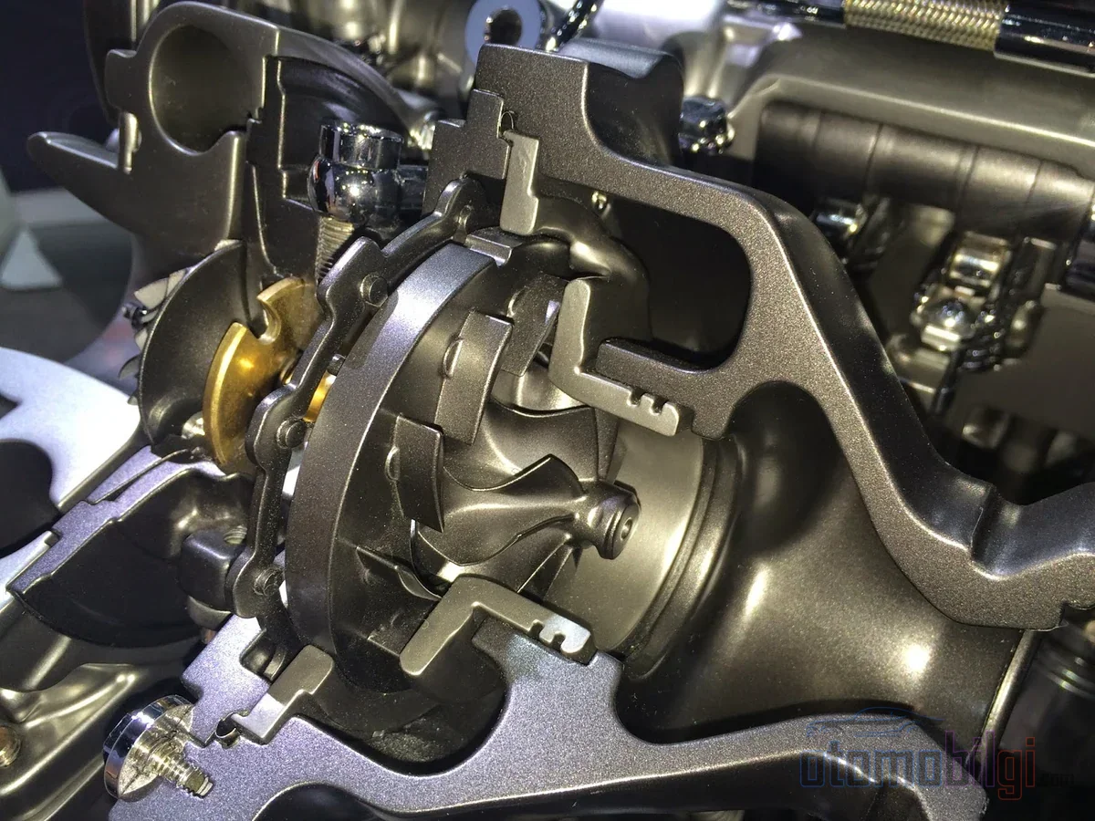
That thick and immediate surge you feel when you accelerate a diesel engine owes more to the choreography of small metal vanes spinning inside the turbine housing than to the magic of the turbocharger itself. Variable geometry turbo (VGT) has become almost a standard solution in modern diesel engines; yet its working principle remains a foggy area for most drivers. On this page, we explain how the vane mechanism works step by step, how it differs from a fixed geometry turbo and a twin-scroll design, and why the technology first spread to diesel and only later to gasoline engines.
Van Before the Turbine: Anatomy of the Mechanism
A classic turbocharger is a two-sided device: the turbine on the exhaust side spins the impeller on the compressor side, sending pressurized air to the engine. Variable geometry turbo does not change this definition; what it changes is how the exhaust gas reaches the turbine. Inside the turbine housing, between the exhaust inlet and the turbine wheel, there is a row of adjustable vanes. These vanes are rotated simultaneously by an actuator - a diaphragm vacuum unit, an electric servo, or a hydraulic unit; when the vane angle and spacing change, the internal flow geometry of the turbocharger is effectively altered as well.
The critical engineering concept is the A/R ratio, that is, the ratio of the turbine housing's cross-sectional dimension to the turbine radius. A fixed geometry turbo is born with a single A/R value, and this value remains valid across the entire rev range. Yet the optimum A/R required at low revs is very different from the value needed at high revs: if the ratio is too large, the turbo cannot produce boost at low revs; if too small, it chokes the engine at high revs, and as exhaust manifold pressure and pumping losses increase, power drops. VGT resolves this dilemma within a single turbo: as the vanes move, the turbine's effective A/R ratio is readjusted according to the conditions.
Highlights
- VGT continuously varies the turbine's effective A/R ratio according to the rev range via the vane angle.
- At low revs the vanes close, exhaust flow accelerates, and turbo lag is largely prevented.
- Variable geometry turbines in most applications do not require a wastegate; the actuator takes over pressure control.
- VGT plays a key role in sustaining EGR flow for the NOx targets of Euro 5 and Euro 6 levels.
- Modern gasoline VGTs are built with materials that can withstand exhaust temperatures above 1000 °C.
How Do the Vanes Produce Torque at Low Revs?
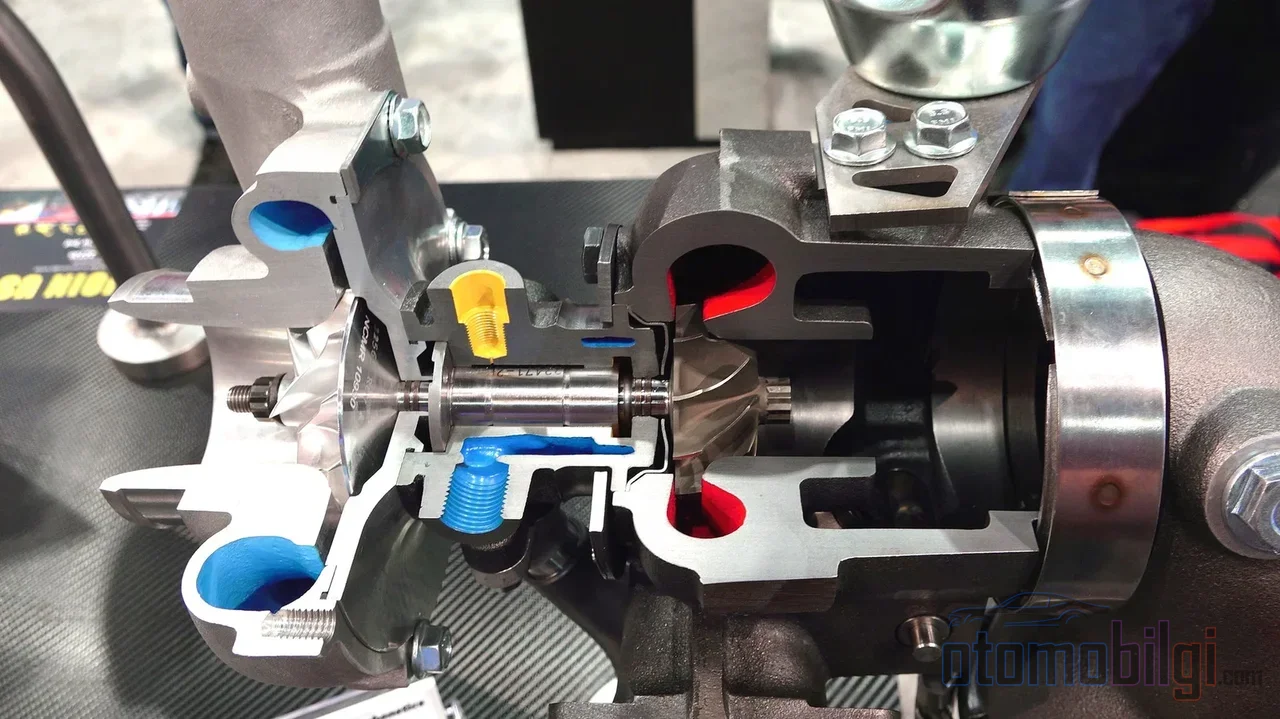
The essence of the mechanism rests on this chain of logic: at low engine speeds, the volumetric flow of exhaust gas is low, yet enough energy is needed to spin the turbine. The solution is to pass the same flow through a narrower passage at higher speed. When the engine runs at low revs, the vanes narrow and close; as the passage between the vanes narrows, the exhaust flow accelerates and is directed toward the turbine wheel at a sharper angle. The result: the turbine spools up earlier, the compressor produces boost earlier, and the engine approaches its expected low-end torque the instant the gas pedal is pressed.
At high rpm, the picture reverses. Since exhaust flow is abundant, the vanes open, the passage widens, and the gas enters the turbine at a looser angle. This prevents excessive back pressure and excessive turbo speed at high rpm; the engine can breathe freely at upper rev ranges as well. The same mechanism also works during transient load changes: at every throttle response, the vane position is repositioned within milliseconds according to the difference between target boost and actual boost.
The price of this continuous adjustment is the shape of the efficiency curve. The variable geometry turbine reaches peak efficiency at approximately a 60% nozzle opening; this value is generally comparable to that of a fixed geometry turbine, or even a few points lower. However, when the opening moves away from this middle position in either direction, turbine efficiency drops rapidly. The gain of the VGT comes not from efficiency at a single point, but from the ability to hold acceptable efficiency across a wide rpm range.
Fixed Geometry, Wastegate and Twin-Scroll Comparison
In a fixed geometry turbine (FGT), the vanes are embedded in the housing; they cannot change angle or position relative to the exhaust flow. This simplicity is also a fate: the turbo is sized either small for low rpm or large for high rpm. To control high boost pressures, the FGT typically uses a wastegate - a valve that bypasses excess exhaust around the turbine.
The variable geometry turbine largely eliminates this need. In most VGT designs there is no bypass; the turbine is sized with the capacity to manage the engine's entire exhaust flow, preventing overboost and overspeed through vane position. Boost control is handled not by a wastegate, but by the actuator. In applications requiring high mass flow - especially high-performance gasoline engines - an additional wastegate can still provide benefits; on the diesel side, it is usually unnecessary.
The twin-scroll turbo approaches the problem from a different angle: it separates the pressure pulses coming from the exhaust manifold into separate channels (scrolls) and delivers them to the turbine in phase-compatible form, reducing lag and increasing low-end torque. Theoretically, it is significantly cheaper than a VGT; therefore it is a reasonable balance in gasoline boosting. However, the twin-scroll's geometry is also fixed - even if there is a valve modulating the flow between the two scrolls, it cannot continuously rewrite the angle of the gas flowing per vane position. The flexibility provided by the VGT means direct authority over the pressure-ratio/flow relationship across the turbine; twin-scroll offers only a subset of this flexibility, with fewer moving parts.
| Feature | Variable Geometry (VGT) | Fixed Geometry (FGT) | Twin-Scroll |
|---|---|---|---|
| Turbine geometry | Continuously varied by vane angle | Fixed | Fixed, dual channel |
| Wastegate requirement | Mostly not needed | Typically present | Usually present |
| Number of moving parts | High | Low | Low |
| Low-end response | Very good | Limited | Good |
| Typical use | Modern diesel engines | Constant load, some performance applications | Gasoline engines |
One nuance is worth noting: in applications like generator engines running at constant load, a fixed-geometry turbine can deliver higher efficiency than a VGT; because the moving part tolerances of the VGT add extra resistance to the exhaust path. The value of variable geometry emerges under operating conditions that vary.
Why Do Almost All Modern Diesels Use VGT?
The invisible partner of emissions legislation
Behind the standardization of VGT in diesel engines, there is not only driving comfort; there is also emissions legislation. Variable geometry, by controlling the exhaust manifold pressure to rise above the intake manifold pressure, makes exhaust gas recirculation (EGR) sustainable - even during transient events like gear changes. This is an integral part of the strategy for reducing NOx emissions to Euro 5 and EPA 10 levels. Most modern VGTs from suppliers such as Garrett, Holset and BorgWarner use electronic actuators; because these complex control strategies can be executed not with a vacuum diaphragm, but with direct commands from the engine control unit.
Exhaust brake and regeneration support
On the heavy-duty side, sliding-vane designs can also be used as an exhaust brake without requiring an additional exhaust flap. Also, the vanes can be moved to positions that deliberately reduce turbine efficiency in order to raise exhaust temperature for the DPF to reach its light-off temperature and for regeneration. In other words, the VGT is not just a part that produces boost, but an active tool of heat and pressure management.
Diesel's thermal advantage
There is a simple physical reason why the technology was adopted in diesels first: the exhaust temperatures of diesel engines are significantly lower than those of gasoline engines, and this creates a more favorable thermal environment for the moving parts in the vane mechanism. On the gasoline side, the situation was different.
VGT in Gasoline Engines: Delayed Spread
For many years, the exhaust temperatures of gasoline engines were too much for VGT vanes; the technology was effectively trapped in the diesel world. Advances in materials technology pulled down this wall: today's gasoline VGTs are made from materials that can withstand exhaust temperatures above 1000 °C. The list of gains is familiar: faster boost response than conventional wastegate turbos, downsizing support, and improved efficiency. Turbocharged engine downsizing is one of the proven ways to improve fuel economy; the VGT is the component of this formula that compensates for the response loss.
The historical timeline is also instructive. The idea of the rotating-vane VGT was patented in the 1950s; Nissan was one of the first brands to try variable nozzle turbos on road cars in 1985, followed by the Honda Wing Turbo in 1988 and the 500-unit Shelby CSX-VNT in 1989. The 1991 Fiat Croma brought VGT to mass production in a direct-injection turbo diesel, while on the gasoline side the most notable step was the 2007 Porsche 911 Turbo (997) with its twin-VGT 3.6-liter engine. The 2015 Koenigsegg One:1, with its twin VGT in the 5.0-liter V8, reached 1361 hp.
Design Types: A Different Vane for Every Task
VGT is not a single patent but a family of solutions. The most common type in passenger cars and light commercial vehicles is the variable nozzle turbine (VNT): the vanes rotate simultaneously around the hub, both the pitch and the passage cross-sectional area change, and the design offers higher flow and higher peak efficiency than the other types. In heavy-duty engines, the sliding wall type is preferred: the vanes do not rotate; the effective width of the turbine changes along the axis; the number of moving parts is lower. The third route is the variable flow turbine (VFT), which uses a twin-volute housing and a blend gate to direct flow between the scrolls - a simpler design with lower flow that can accommodate a wastegate when needed.
The Failure Side: The Price of Flexibility
Moving parts mean potential for wear. In diesels, clogging of the vanes due to soot production is a common failure mode; if the vanes cannot be positioned correctly, boost and performance control degrade. Typical symptoms include loss of power, poor acceleration, low boost pressure, excessive black smoke, and the engine warning light. Continuing to drive with a faulty VGT can lead to DPF problems, loss of performance, and eventually engine damage. For this reason, in the aftermarket world VGTs usually remain limited to manufacturer (OEM) applications due to the coordination required for the optimal vane position; advanced engine management systems and aftermarket control units can partially overcome this barrier. The debate in performance circles about returning to fixed geometry can be summarized this much: the flexibility VGT provides is traded off against the weight and complexity it brings in some racing and high-power applications.
Summary: How Does Variable Geometry Turbo Work?
The short, quotable answer is this: A variable geometry turbo continuously readjusts the angle and speed at which exhaust gas enters the turbine according to the rev range, by opening and closing the vanes around the turbine; at low revs, the narrowed vanes accelerate the flow and produce boost early, while at high revs the opened vanes limit backpressure. This way, a single turbo does the job of both a small and a large turbine at once: turbo lag is reduced, the torque curve broadens, and a wastegate is often no longer needed. In the diesel world, this mechanism has become a cornerstone of emissions, EGR, and heat management rather than a comfort feature; on the gasoline side, however, the same logic feeds the responsiveness of downsized engines as long as material technology allows. The vanes are small - but it is precisely they that write the character of the modern turbocharged engine.