The Invisible Brain of the Battery: What Does the BMS Do?

Share This Page
BMS, or battery management system, is the electronic control layer that monitors, protects, and estimates the condition of each individual cell in an electric vehicle battery; it measures cell voltages and temperatures, balances cells against each other, prevents overcharging and deep discharge, applies safety cutoffs, and calculates the range estimate shown on the dashboard. Lithium-ion cells are among the chemicals with the highest energy density, but they have a correspondingly narrow safe operating window; going outside this window leads first to performance loss and later to dangerous failures. The system that watches over this narrow window, constantly performs calculations, and cuts the circuit when necessary is the BMS. While the pack's power comes from its cells, the pack's lifespan and safety come from this "invisible brain."
Key Highlights
- The BMS audits not only the entire pack but also each cell and cell group individually
- The ideal operating temperature for lithium-ion cells is approximately 30-35 °C range
- Below 0 °C, charging creates metallic lithium plating on the anode and causes permanent damage
- Passive balancing is typically limited to 0.25 A, while active balancing supports up to 6 A supports up to
- SOC is a quantity that cannot be measured directly; the most common estimation method is Coulomb counting
What Does the BMS Do? The Complete List of Its Duties
A battery pack is formed by arranging the cells into a matrix of rows and columns. The BMS's scope of supervision falls under five headings: monitoring the battery, protecting it, estimating its operational status, continuously optimizing performance, and reporting status information to external devices. The critical point is this: these monitoring and control functions are applied not over the whole pack but over individual cells or cell groups (modules). Even if the pack shows a total of 400 volts, the BMS's real concern is the current voltage of each individual cell.
These five tasks cannot be considered separately. Without monitoring data, protection is impossible; without protection, optimization loses its meaning; and the data derived from all of these feeds the range and health estimates. In other words, the BMS is not the name of a single sensor or a single algorithm, but the entirety of an interconnected control chain.
The three fundamental measurements: voltage, current, and temperature
Everything starts with measurement. The BMS continuously measures each cell's voltage and the pack's total voltage; this way, overcharging and over-discharging are prevented before they occur. Charge and discharge current is monitored with a separate measurement, and usage conditions are evaluated based on these currents. On the temperature side, NTC thermistors inside the module report each cell's temperature continuously.
The importance of cell-level temperature monitoring should not be underestimated: in addition to enhancing safety, it directly affects the battery's lifespan and fast-charging performance. Knowing from the pack average that one region in a module is heating up is not enough; the problem is always in the hottest or coldest cell, not in the average.
Overcharging and Deep Discharge: Two-Way Protection
A lithium-ion cell has different current limits for charging and discharging, and manufacturers specify these as continuous and peak current limits. The BMS tolerates short-term high demands by integrating peak currents; for example, the current demand during sudden acceleration falls into this category. But in extreme cases such as a short circuit, where the limits become meaningless, it cuts the current immediately.
Things get more delicate as the upper voltage limit is approached. The BMS may demand a gradual reduction or complete interruption of the charging current; a mechanism called voltage hysteresis also prevents the control from oscillating by constantly switching on and off. On the discharge side, when the cell voltage approaches the lower limit, the torque delivered to the traction motor in an EV can be reduced. The driver feels this as "the car is holding itself back," but what is happening behind the scenes is keeping the cell out of the chemically harmful zone.
The physics behind torque reduction or current cutoff is simple: an overcharged cell converts the extra energy it receives into heat, and the voltage rapidly climbs to dangerous levels. On the other hand, in a lithium-ion cell that stays at low voltage for a long time, copper dendrites can grow on the anode; self-discharge increases and a safety risk arises. This is why a good BMS keeps monitoring the cells even while the vehicle is parked.
Safety cutoffs and the junction box
The over-discharge cutoff automatically interrupts the discharge circuit a very short time before the voltage drops to a chemically damaging level. The discharge cutoff voltage varies by chemistry; for lithium-ion it generally corresponds to the 2.5-3.0 volt range. A similar logic applies to temperature: at excessive temperatures, the BMS first reduces charge and discharge rates, and if necessary cuts the connection completely.
All of this requires the pack to be managed from a single point. The junction box protects the battery by cutting the power source in the event of a fault, and also contains a ground fault detection circuit. The contactors that make the pack's main connection are also part of this chain as electrically actuated switches. In short, the BMS is not just a system that measures, but one that physically disconnects the circuit when necessary.
Thermal Protection: Keeping the Goldilocks Zone
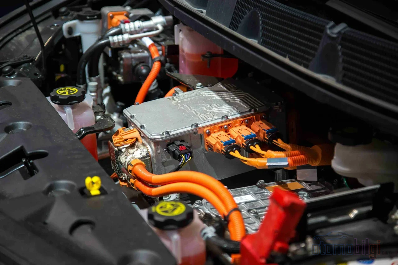
One of the areas where the lithium-ion cell is most sensitive is temperature. The ideal operating zone, known in the literature as the "Goldilocks zone," is a range of approximately 30-35 °C. Seen in numbers, the cost of staying outside this range is clear: a battery operating optimally at 20 °C can lose up to 20% of its efficiency at 30 °C; continuous charge-discharge at 45 °C can raise this loss to 50%.
On the cold side, the taboo is even clearer. Most lithium-ion cells cannot be fast-charged below 5 °C and should never be charged below 0 °C. The reason is physical: at low temperatures, lithium ions cannot properly settle into the anode during charging, and metallic lithium plating forms on the anode. This is permanent damage; it causes capacity loss as well as failure sensitivity. This is the reasoning behind a BMS rejecting fast charging in cold weather without battery preconditioning.
Keeping the temperature within this narrow range is not the BMS's job alone; it works in constant interaction with the thermal management system. Cooling is provided by air flow in passive methods, and by a fan or an ethylene-glycol liquid cooling circuit (pump, heat exchanger, cooling plate) in active methods. The BMS manages these circuits by opening and closing valves and maintains the narrow temperature range.
Balancing: Keeping the Cells Alive Together
Every pack made up of series-connected cells eventually faces the same problem: the cells diverge. Differences in self-discharge, manufacturing variations, cycle-related aging, and temperature differences create capacity and state-of-charge differences between cells. Without balancing, the pack is held captive to the capacity of the weakest cell and can become unusable over time. By monitoring each cell individually, the BMS eliminates these performance differences through balancing and ensures that the cells operate uniformly.
The difference between passive and active balancing
Passive balancing is the easiest method to implement: with a transistor switch and a discharge resistor, the surplus of the cells with the highest charge is dissipated as heat. It is simple and cheap, but what it actually does is burn energy; it pulls the pack down to the level of the weakest cell.
Active balancing, on the other hand, transfers energy between cells using capacitive or inductive storage elements instead of converting it into heat: energy taken from a full cell is moved to a weak cell. It is superior in terms of efficiency and battery life. The difference can also be expressed numerically: while passive balancing is typically limited to a current of 0.25 A, active balancing supports up to 6 A. Which one is chosen is an engineering decision based on the pack and the application; the design choice between the simplicity of passive and the efficiency of active balancing continues.
The common input for balancing algorithms is the SOC estimate. By comparing the estimated SOC values, the BMS decides what to do with each cell.
How Are SOC, SOH, and Range Estimated?
The percentage and estimated range on the dashboard are the most visible outputs of the BMS, but behind them lies not direct measurement but estimation. SOC, or state of charge, is the ratio of the current charge to full charge; however, it is a quantity that cannot be measured with a physical sensor and is estimated using various techniques.
The simplest and most widely used method is Coulomb counting: the current is integrated over time to calculate the charge flowing into and out of the cell. Voltage curves are also used as supporting information. SOH, or state of health, is the ratio of the battery's remaining usable capacity to its original capacity and reflects physical degradation; together with SOH, remaining useful life (RUL) can also be estimated. The BMS's balancing algorithms are based on SOC estimation, and the SOH calculation is likewise based on SOC data; the three quantities feed into each other.
The final step is reporting: by transmitting the cell data it collects to external devices, the BMS presents the remaining energy, the estimated range based on current usage, and the battery health on the instrument panel. This is why the range estimate changes according to your driving style; the estimate is a live calculation that uses instantaneous usage data.
BMS Architectures and Communication with the Vehicle
There are four basic architectures for how the BMS is placed inside the pack, and each strikes a different balance between wiring, cost, and maintenance.
| Architecture | Key feature | Balance |
|---|---|---|
| Centralized | A single BMS unit | Economical and compact, but requires many cables and connections |
| Modular | Repeating modules | Easy to maintain, slightly higher cost |
| Master/Slave | Slaves only transmit measurements, the master performs the calculations | Lower cost |
| Distributed | Electronics located on the monitored cell/module | Wiring is reduced, but fault detection is difficult and cost is high |
Connection with the vehicle, meanwhile, is established through communication protocols: the BMS communicates with external equipment via protocols such as CAN and Ethernet, and uses components such as chip varistors for ESD protection. The battery drive unit, known as the BDU, works in integration with the BMS to support safety, real-time diagnostics, and thermal runaway prevention functions. In other words, the BMS is not an isolated controller inside the pack, but a node connected to the vehicle's overall control network.
The BMS of the Future: Artificial Intelligence and High Voltage
The BMS has become one of the fastest-evolving components on the software side of the vehicle. The focus of academic studies dated 2025-2026 is concentrated in three areas: comprehensive reviews of active cell balancing methods, SOC estimation techniques, and data-driven SOH estimation. It is claimed that BMS systems supported by artificial intelligence and machine learning provide improvement over classical methods, especially in SOH and RUL estimation; when classical methods such as Coulomb counting remain sufficient, and where machine learning offers genuine contribution, remains a design question that is still under debate.
On the hardware side, the direction is clear: the transition from 400-volt architecture to 800 volts and beyond, demand for heat resistance and high precision in temperature and voltage control - these are described as the three fundamental features expected of tomorrow's BMS components. The market confirms this trend with numbers: the automotive BMS market is valued at $4.86 billion in 2025, with annual growth of 18.6% expected between 2026 and 2035. For the EV BMS market, a volume of $7.44 billion in 2025 and a forecast of $9.4 billion for 2026 are given. Additionally, battery SOH analytics - the business of monitoring battery health through software - has already become a $1.59 billion market in its own right in 2026, and is expected to reach $3.2 billion by 2030, with annual growth of 19.1%. Since these three figures use separate market definitions, they are not added together, but they point in the same direction: investment in the battery's brain is increasing rapidly.
Conclusion: The Page of Control, Not Power
When talking about a battery pack, attention usually goes to energy density, range, and fast-charging times. Yet all three of these are the result of the BMS keeping the cells within a narrow safe operating area. There is no protection without measurement, no balancing without protection, and no accurate range estimation without balancing. It is the least visible yet most continuously working system in the vehicle; you cannot see it when you open the hood, but it listens to every cell every second and cuts the circuit when necessary. The better the battery, the more quietly the system managing it does its job.
Sources
- What is a Battery Management System (BMS)? – How it Works
- What Is BMS in an Electric Vehicle (EV)?
- What Is Battery State of Charge? - MATLAB & Simulink
- Active Balancing: How It Works and Its Advantages
- Battery Protection - BMS Functionalities
- Active and Passive Battery Pack Balancing Methods
- A Comprehensive Review of Active Cell Balancing
- SOC and SOH in BMS
- AI‐Driven Battery Management for E‐Mobility
- Advanced Battery Management Systems (BMS) for Electric Vehicles
- Automotive Battery Management System Market
- Electric Vehicle Battery Management System Market
- Battery State-of-Health Analytics Market Report 2026