Why Haven't In-Wheel Motors Become Widespread Yet?
Share This Page
An in-wheel motor is a drive architecture in which the electric motor is placed directly in the wheel hub, eliminating all drivetrain components such as the transmission, differential and drive shafts. Although its advantages are very strong on paper, it has not become widespread in mass-production electric vehicles to date due to increased unsprung mass, challenging thermal management, sealing problems and high costs.
Highlights
- The ancestor of in-wheel motors dates back to an 1884 patent; the hybrid car application, on the other hand, goes back to 1899.
- The most common motor type is the brushless DC (BLDC); its lifespan is on the order of roughly 5,000 hours versus 20,000 hours for brushed types.
- Temperatures above 140 °C can cause permanent magnets to permanently lose their magnetism.
- Increased unsprung mass accentuates the secondary resonance in the suspension, which lies in the roughly 7-10 Hz band.
- As of 2026, the first mass-production steps are being taken: one manufacturer aims to bring a 220 kW -class in-wheel motor to mass production.
How Does an In-Wheel Motor Work?
The principle is based on electromagnetic induction, as in every electric motor. A phase controller regulates the timing of the current in the stator windings; the rotating magnetic field, formed according to signals from position sensors, interacts with the permanent magnets in the rotor and turns the rotor - that is, the wheel. There is no chain of clutch, transmission, differential and drive shaft; power is transmitted to the wheel right where it is generated.
A modern in-wheel motor is more than just a drive unit on its own. Direct drive, regenerative braking and energy recovery together with friction braking, electronic differential speed control, and air or water cooling all come together inside the same compact housing. On the control side, two approaches stand out: motors with Hall sensors provide very precise control at low rpm, while sensorless motors estimate the rotor position by measuring back EMF (BEMF) and struggle to produce torque at very low rpm.
Outer-Rotor and Inner-Rotor Designs
There are two basic architectures in in-wheel motors. In the outer-rotor design, the rotor surrounding the wheel rotates at low speed - approximately 1,000-1,500 rpm - and offers silent, direct drive; the structure is simple but power density is limited. The inner-rotor design, on the other hand, operates at high speeds reaching 10,000 rpm and reduces this speed to wheel speed through a fixed-ratio planetary transmission. The intervening gear set makes it possible to produce the same power with a smaller and lighter motor; compact planetary gears make inner-rotor types seriously competitive in power density. The architectural preference debate is still ongoing: simplicity, or power density?
Winding technology is another variable that determines power density. Hairpin-shaped rectangular copper wires, called hairpins, allow much denser packaging, better heat dissipation, and therefore higher power density compared to round-wire windings. Getting more power out of a given volume is the most direct way to make the motor's job easier within the tight space inside the wheel.
Why Is the Architecture Appealing? Parts Removed and Advantages Gained
Moving the motor to the wheels in an electric car radically simplifies the mechanical structure. The clutch, gearbox, differential, and drive shaft disappear entirely; this reduces mechanical losses in the drivetrain to zero. Torque is transmitted directly to the wheel without intermediate joints - no cardan, no universal joint - and responds at the same instant as the driver's foot.
The effect of simplification reads even more clearly in a list:
- Thanks to independent drive of each wheel, front-wheel, rear-wheel, and permanent 4x4 drive can easily be implemented with a single architecture.
- The volume allocated inside the chassis for the motor and gearbox is freed up; that space is converted into passenger, cargo, or extra battery capacity.
- With fewer moving parts, operation becomes quieter, and mechanical wear and maintenance needs drop.
- Since weight is spread across all four corners, the center of gravity lowers, contributing to stability.
On the efficiency side, the math also works in favor: compared to a centrally motorized system, electric vehicles with in-wheel motors offer higher system efficiency and lower mechanical losses. Mechanically, the vehicle is simplified; electrically, it is a far smarter vehicle - because the torque of the four motors can be managed independently on a millisecond scale.
The Unsprung Mass Problem: The Weight Handed Over to Suspension Control
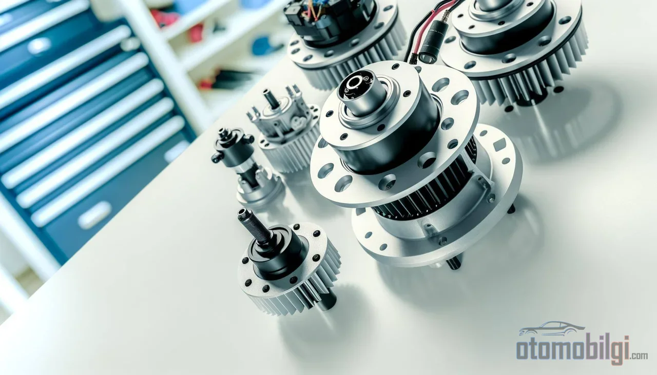
The most debated cost of the in-wheel motor is its contribution to unsprung mass. Sprung mass is the mass carried by the body, while unsprung mass is the mass managed directly by the wheel and suspension, bypassing the spring. When the motor is moved inside the rim, this second mass increases significantly, and the consequences become measurable: road holding, ride comfort, suspension responsiveness, and component durability are negatively affected.
Physics is simple and merciless. Increased unsprung mass weakens the wheel's ability to follow the road profile, amplifies the wheel's dynamic load and suspension oscillation, and sharpens the secondary resonance mode in the roughly 7-10 Hz band, degrading comfort. Although the effect of this on the body varies from vehicle to vehicle due to the filtering effect of the axle distance, every extra kilogram not controlled by the suspension is ultimately paid for by the tire in contact with the road.
At this point, there is a counterargument that should not be ignored. The technology's producers claim that the unsprung mass effect is exaggerated and that well-tuned suspension and active dampers can largely offset this effect. However, peer-reviewed studies of recent years confirm that the increase in unsprung mass measurably amplifies the wheel's dynamic load and suspension oscillation. The realistic picture is this: the problem is not insurmountable, but neither should it be taken lightly - compensation is possible with a more advanced and more expensive suspension design.
Heat Management and Sealing: The Hostile Environment Inside the Wheel
Heat Trap in a Cramped Housing
In a centrally motorized vehicle, the motor sits in an area with easy access to the cooling circuit and contact with fresh air. Inside the wheel, however, the same motor operates in a cramped housing, heated by brake heat and exposed to road splash. Dissipating heat in this space is difficult; overheating first reduces motor efficiency, then rapidly degrades the insulation and can lead to failures in electronic components, even as severe as short circuits. The critical threshold is also clear: above 140 °C permanent magnets can lose their magnetism - meaning a single long, high-load climb can permanently weaken the motor. The extra load that unsprung mass places on the brakes further increases the heat generated. The direction of the solution is known: liquid cooling channels, advanced heat sinks, and low-resistance winding materials. Heat dissipation in a large-capacity in-wheel motor in the 35 kW class has been experimentally verified with an internal cooling system; so it is a technically solvable problem, but every solution adds cost and weight.
The Battle of the Seals: Water, Dust, and Vibration
The second environmental problem is sealing. The motor is inside a component spinning at road speed; surrounded by moisture, dust, mud, salt water, and constant vibration. While every component above the spring is somewhat protected from this environment, the motor inside the wheel fights on the outermost line of the buffer. The seal's task requires a two-way balance: while providing high sealing, it must not add friction losses to the rotating part. For this reason, in-wheel motor seals are specially designed to reduce friction losses at increasing speeds; scalable seal geometries and sealing arrangements that export friction heat outward to suppress seal temperature are being developed at the patent level.
Failure analyses also confirm the results: the effect of unsprung mass on driving dynamics, sealing difficulties, and acoustics are among the prominent failure sources in in-wheel motors. There is also an economic dimension: the wheel hub is one of the areas most vulnerable to accident damage; when damaged, the part to be repaired is no longer a simple wheel rim, but an expensive unit containing a motor, power electronics, and seals. It is not surprising that the cost of a highly efficient, lightweight four-wheel-motor system is still high.
Comparison with the Central Motor: The Calculation of Two Architectures
Today, almost all electric cars on the road use a single- or dual-central-motor architecture. In this layout, the motor and reducer sit on the axle, in an area protected by the body; it offers a mature production chain, proven thermal management, and acceptable unsprung mass. The in-wheel motor, on the other hand, does the same job with four compact units and takes on the challenges listed above. It would be appropriate to summarize the difference in a table:
| Feature | Central Motor | In-Wheel Motor |
|---|---|---|
| Drivetrain components | Transmission, differential, drive shaft | None - direct drive |
| Mechanical loss | Drivetrain losses present | No transmission losses |
| Packaging | On the axle, takes up volume | In the wheel hub, frees up the chassis |
| Unsprung mass | Low | Increases significantly |
| Heat and sealing environment | Protected area | Directly exposed to road conditions |
| Torque vectoring | Requires an additional mechanism | Natural attribute - control per wheel |
| Cost and maturity | Proven in mass production | High cost, limited production experience |
This table also explains why the technology still remains in niche applications. In the world of electric bicycles and scooters, the hub motor has already become the standard thanks to its simplicity and low cost; in light mobility, unsprung mass and thermal load are a much smaller problem than in a car. At the automobile scale, however, the equation changes: as mass, power, and braking energy grow, all four problems intensify proportionally.
Torque Vectoring: The Technology's Strongest Card
The least debatable of the in-wheel motor's advantages is its control capability. When each wheel has its own motor, applying different torque to different wheels is a matter of a software parameter. Torque vectoring assists the vehicle's turn by accelerating the outer wheel and slowing the inner wheel in a corner, and can noticeably improve road holding. No mechanical differential is required; an electronic differential independently adjusts the speeds of the inner and outer wheels in a corner.
Control strategies are also maturing: stability control for electric vehicles with in-wheel motors has been developed by combining integrated torque vectoring and active front steering. On the other hand, how quickly control becomes more complex, and how the processing power required by traction control and vectoring algorithms will affect system cost, remain open questions in engineering circles. In short, the technology's strongest card is also the justification for its most complex subsystem.
Is the Window of Wider Adoption Opening? Current Picture
History unfolds in an interestingly cyclical way. The first electric hub motor patent was filed in 1884, the patent for an electric bicycle with a front-wheel hub motor in 1895, and in 1899 one of the first hybrid automobiles, combining a four-battery hub motor with a gasoline engine, was developed. In other words, the technology is as old as the automobile itself; yet the unsprung mass and battery problems that held it back in the early days have been waiting to be solved for over a century.
Today, the picture is starting to move. In recent years, one manufacturer announced a production-ready in-wheel motor system targeted for mass production in 2026, and in the fall of 2025 it introduced a new hub motor with 220 kW of power, reporting that a European manufacturer plans to use this technology in an electric sports car. A homologated in-wheel motor technology from a competing supplier, already used in production vehicles, has accumulated over 1.5 million miles of test runs across more than 100 vehicles; the same company introduced a new model dedicated to high-performance electric vehicles in October 2025. An in-wheel drive solution with an integrated damper, showcased at CES 2026, was interpreted as a response to the technology's well-known wheel bearing load problem.
Projections on the market side should be read with caution. Forecasts published for the in-wheel motor market, taking 2026 as the base year, vary across a wide range of approximately $2.17-4.55 billion; 2034 targets likewise fall within a band of $31-70 billion depending on the estimate, with an annual growth rate projected at 28-41%. This spread shows that the market has not yet settled in terms of definition and scope - but the direction is the same in every forecast: upward. A recent peer-reviewed review also sums up the situation: despite their space and efficiency advantages, direct-drive in-wheel motors have not yet been widely integrated into electric vehicles.
So Why Doesn't Every Electric Car Have Four In-Wheel Motors?
The answer to the question doesn't fit in a single sentence, but it fits into four items: unsprung mass, heat, sealing, and cost. The central motor solves all four problems in one stroke; in return, it pays with some mechanical efficiency and packaging flexibility. The in-wheel motor makes exactly the opposite trade: it gains in transmission losses, packaging volume, and torque vectoring capability; in return, it complicates suspension design, pushes thermal and sealing engineering to the highest level, and raises component cost.
As of 2026, the technology stands at the threshold of mass production: the first homologated applications have been made, production-ready systems have been announced, and engineering answers have been produced for classic weaknesses such as bearing load and heat management. The key to widespread adoption is not a single invention; it is the convergence of affordable adaptive suspension that compensates for unsprung mass, manufacturing that achieves economies of scale, and the risk appetite of automakers at the same point. When that convergence happens, the drivetrain architecture that has remained unchanged for the past century of the automobile will be radically renewed for the first time.
Sources
- Types, Pros & Cons - What is a Hub Motor & How Does It Work
- Principle, Advantages & Disadvantages of Hub Motor
- In-Wheel Motors and Unsprung Mass. Does It Matter?
- Making the Case for In-Wheel Motors
- Evaluation of the Unsprung Mass Effect on Ride Comfort of In-Wheel Motor Vehicles
- Temperature Field Analysis and Heat Dissipation of In-Wheel Motors
- Hub Motors' Heat Dissipation Problems and Solutions
- Sealing the Future of In-Wheel Motors: Low Friction and Maximum Protection
- Critical Review of Direct-Drive In-Wheel Motors in Electric Vehicles
- Protean Electric Unveils New 220 kW Wheel Hub Motor
- Elaphe Propulsion Technologies
- In-Wheel Motor Market
- In-Wheel Motor Market
- In-Wheel Electric Motors Gain Traction Again