What Is Hairpin Winding and What Does It Bring to the Electric Motor?
Share This Page
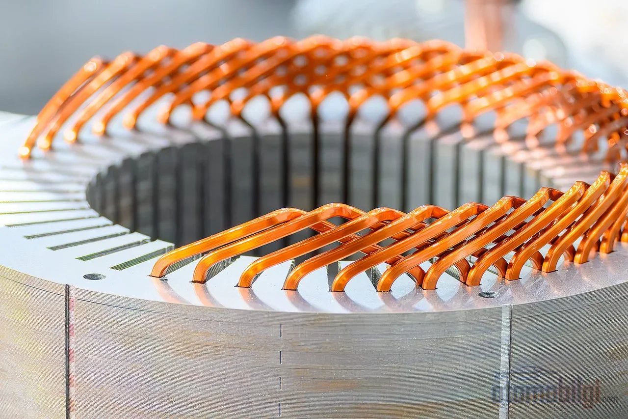
Hairpin winding is the use of U-shaped bent rectangular copper bars in place of the round copper wires in an electric motor's stator. This geometry fits more copper into the slot, raising the fill factor from the 45-50% level of classic winding to above 70%; it provides a stronger magnetic field, less electrical loss, and better thermal management. On this page, we examine the structure of hairpin winding, its manufacturing process, its efficiency and power density gains, its limits, and which manufacturers have switched to this technology.
Highlights
- Hairpin winding provides a copper fill factor of 70% or higher in the stator slot; in classic round wire winding, this value is typically between 35-50%.
- The technology was first used in a series production vehicle with the 2008 Chevrolet Tahoe hybrid .
- Hairpin advantages are supported by a validated design guide on a motor with permanent magnets inside, delivering 160 kW of power at 18,000 rpm. overcoming them in a motor with permanent magnets inside, backed by a validated design guide.
- A larger conductor cross-section can create additional AC losses at high frequencies due to the skin effect; hairpin is not superior in every condition.
What Is Hairpin Winding and How Does It Differ From Classic Wire Winding?
What determines an electric motor's torque is the magnetic field generated by the current passing through the stator slots. The geometry of the conductors carrying this current directly affects how efficient the motor is. In classic winding, enamel-insulated round copper wires are wound into the slots; because the wires are round, it is impossible to eliminate the voids within the slot. In hairpin winding, the same job is handled by rectangular cross-section copper bars that are bent at the ends and welded to one another.
The rectangular cross-section is not mathematical elegance but a physical gain: rectangular bars fill the slot's rectangular void much more tightly. The more area is filled, the stronger the magnetic field for the same current and the more copper for the same volume. The rest of the stator - the lamination stack, housing, cooling architecture - remains largely unchanged; the innovation is entirely concentrated in the winding system.
Three Winding Variants: U-pin, I-pin, and Continuous Hairpin
The most common member of the hairpin family is the U-pin structure: the copper wire is bent into a U shape, and its two open ends enter from the two sides of the stator, where they are bent and welded. In the I-pin variant, straight, unbent pins are used; electrical contact is required from both sides, but the fill factor is approximately 4% higher than U-pin, reaching up to 74%. Continuous (continuous/wave) winding is formed by bending a single wire in a serpentine shape over meters and is inserted from the inner diameter as a winding mat; its greatest distinction is that it does not require the welding process of U-pin.
There is also a unique architecture on the insulation side. Insulation paper is placed between the slot and the lamination stack; the conductors themselves are coated with varnishes in high temperature classes such as polyamide-imide (PAI), PEEK, or PAI+FEP. The welded ends are re-insulated after the process with powder coating or polyurethane resin.
Copper Fill Factor: The Key to Efficiency
The fill factor measures the ratio of area occupied by copper in the cross-section of the stator slot. Values shift slightly between sources depending on how "copper" is defined; the typical range for round wire is given as 40-50%, for hairpin 60-73%, and above 75% in some modern designs. The magnitude of the difference, however, is beyond dispute: hairpin fits around 20% more conductor into the same motor volume.
| Feature | Round Wire Winding | Hairpin Winding |
|---|---|---|
| Copper fill factor | Approximately 40-50% | 60-73%, above 75% in modern designs |
| Conductor cross-section | Round, multi-strand | Rectangular bar |
| End-winding | Irregular, bulky | Regular, compact |
| Stator lacing | Required | Not required |
| Manufacturing | Mostly manual labor | Suitable for full automation |
The impact of this picture on motor performance is read in three stages. First, more copper means a stronger magnetic field and higher torque. Second, the optimized winding path shortens the conductor length; DC resistance and copper loss drop, the same power is produced with less energy, and the vehicle's range increases. Third, a more tightly packed stator can be made smaller - this is the physical reason for the increase in power density.
Thermal Performance: Why Does It Manage Heat Better?
In an electric motor, heat arises from losses in the conductors. Hairpin winding provides a two-fold gain here: lower copper loss generates less heat; and the regular, compact end-winding structure distributes the generated heat so that it can be carried away. While the air gaps between the randomly arranged conductors in round wires act like thermal insulation, the hairpin's orderly geometry eliminates these gaps.
The result is a higher current-carrying capacity per conductor and easier temperature management. Especially when evaluated together with oil spray cooling, hairpin winding stands out as a solution that increases both efficiency and power density in electric vehicle motors. A lower and more homogeneous operating temperature also extends the life of the insulation system, directly improving the motor's reliability.
How Advantageous Is Hairpin at High RPM?
Things do not progress in one direction here. The hairpin's large conductor cross-section can become a disadvantage at high frequencies: a current displacement effect known as the skin effect causes current to flow only through the surface layer of the conductor, increasing the effective resistance. Since frequency rises as RPM increases, the hairpin's superiority in DC losses can be partially dissolved by AC losses at high RPM. Therefore, increasing the fill factor does not provide an advantage in every design goal; the gains depend on frequency, current, and insulation design.
Still, the practical success stories are strong: the advantages of hairpin, 160 kW of power and 18,000 rpm verified with a comprehensive design guide in a permanent magnet motor. In high-speed PMSM motors, the key parameters of hairpin versus flat wire winding are still an active research topic today. There is also an interesting contradictory piece of data: in a driving cycle comparison, the more resource-intensive continuous-wound IPMSM variant proved 0.63% more efficient in the WLTP cycle. The difference is small but the message is clear: hairpin does not automatically win in every condition and every cycle.
The balanced summary is this: hairpin is a technology that will complement, not destroy, the classic winding. When production and lifecycle costs are taken into account, the net difference in most applications is more modest than the fill factor figures suggest.
How Is a Hairpin Stator Manufactured: A Four-Step Production Chain
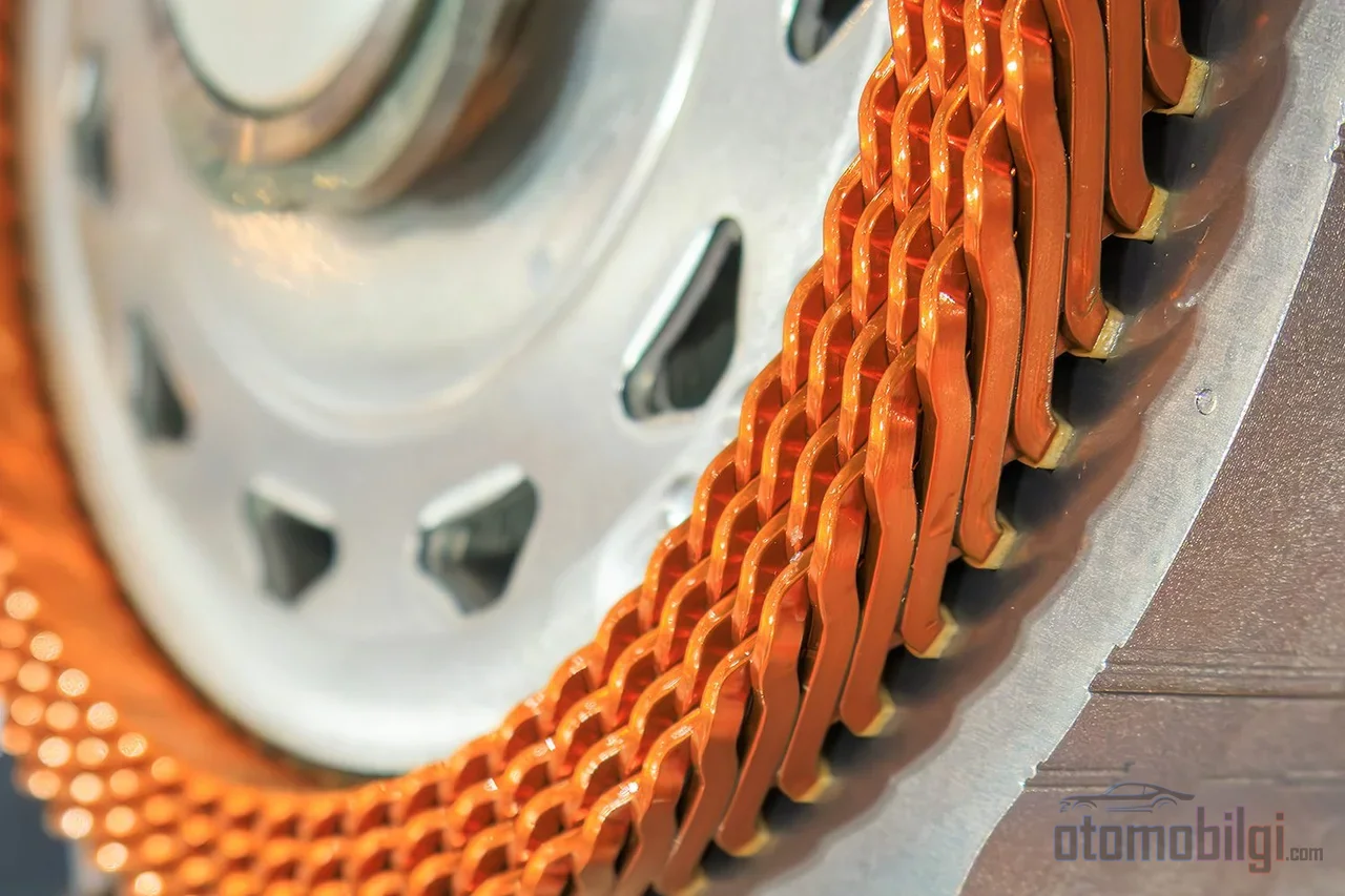
The production story of hairpin is the second half of why this technology is so appealing. The process is suitable for end-to-end automation, and a typical line consists of wire forming, insertion, spreading, twisting, cutting and welding stations. Short cycle times and rising production volumes reduce the unit cost.
- Forming: Flat copper wire is unwound and flattened, the insulation is partially stripped by laser or mechanically for welding, cut to length and bent. Seamless insulation on the bend is the most critical constraint of the twisting process.
- Insertion: Pins are inserted axially into the stator stack. A single hairpin stator typically uses 3-16 different hairpin geometries. is used.
- Twisting and welding: The ends, twisted according to the end winding scheme, receive electrical contact via laser welding; the goal is a homogeneous weld geometry and minimum thermal input. Laser stripping is more consistent and precise than rotating brush mechanical abrasion - as the brushes wear, they also wear the copper.
- Insulation and impregnation: The welded ends are re-insulated with powder coating or polyurethane resin; the coating protects against oxidation and moisture, and the entire stator is impregnated.
In traction applications, the main challenge is process reliability. Relative height differences or lateral offsets at the hairpin ends can lead to welding defects; a faulty weld can render the motor inoperable, beyond the additional electrical loss. For this reason, three different joining technologies - resistance, laser and micro TIG - are actively being compared. In addition, the limitations of the continuous hairpin technology process chain are being examined as a separate engineering topic.
Which Manufacturers Have Switched to Hairpin Winding?
The technology's series production journey starts surprisingly early: the first use was seen Chevrolet Tahoe hybrid's 2008 model in the two motors of the 2ML70 transmission. The Chevrolet Volt was also equipped with a hairpin motor developed by Remy. The real proliferation, however, came in the electric vehicle era.
The Volkswagen Group today uses hairpin stators in models such as the ID.3, ID.4, Audi e-tron GT and Porsche Taycan. BMW's first hairpin-equipped model was the iX3. GM, 2021'de introduced a new motor series with hairpin, ranging from the hybrid ASM's 64 kW to the Hummer EV's 255 kW PSM. Tesla, for its part, 2023 announced that it will use hairpin in its next-generation motor. JLR is also among the manufacturers that announced using the technology in production. On the R&D side, BMW-backed Pro-E-Traktion and RWTH Aachen's HaPiPro2, KIT's AnStaHa and FAU Erlangen-Nürnberg's IPANEMA, KIPrEMo and KIKoSA projects reflect the industry-academia collaboration in this field. On the supply side, players such as BorgWarner, Denso and Hitachi are cited as the market's key decision-makers.
Is Hairpin the Right Choice for Every Motor?
In engineering practice, the answer depends on the application's operating profile. In traction motors that demand high torque and power density at low-to-mid revs, hairpin's DC loss and thermal advantages readily turn into profit; automation-friendly production provides economies of scale. On the other hand, in applications that run at continuously high frequencies or whose production volume does not justify the automation investment, classic winding is still a sensible choice and will continue to exist for the years ahead. The designer's job is to choose not the highest number in the fill factor table, but the winding that yields the lowest total loss and cost in their own cycle - hairpin is often the winner of this calculation, but not always.
Sources
- What is a Hairpin Motor - Benefits & Assembly Process
- Hairpin technology
- A closer look at hairpin motor windings
- Thermal management of hairpin winding traction motors
- A comparison between continuous and hairpin windings for electric traction drives
- A Comprehensive Design Guideline of Hairpin Windings
- Round Wire vs. Hair Pin Motor Winding Guide
- Comparison of I-pin, Hairpin, and X-pin
- Hairpin Stator Solutions for E-Motor Manufacturing
- Hairpin stator welding: comparing 3 joining technologies
- Hairpin Winding Motors: Slot Fill, AC Losses, and Manufacturing Defect Control