IPM vs SPM: Magnet Placement in EV Motors
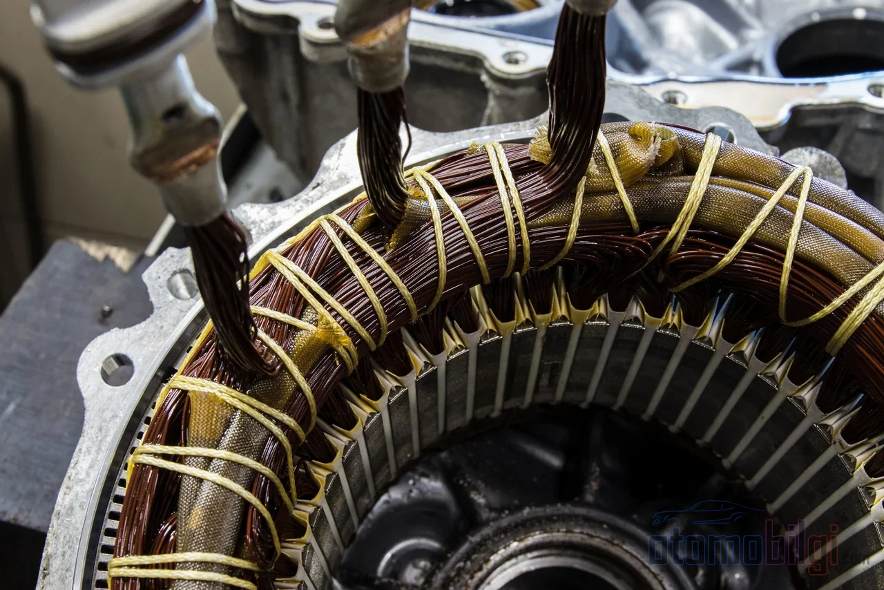
At the heart of most electric cars is a motor that runs in sync with the magnetic field of the rotating rotor: the permanent magnet synchronous motor. But the truly interesting part is where the magnets sit on the rotor. In almost all of the new-generation electric vehicle platforms entering the market today, the magnets are not glued to the surface of the rotor but embedded in cavities carved into the rotor body. While the surface permanent magnet (SPM) design dominated the permanent magnet motor market for decades, why has the automotive industry turned to the interior permanent magnet (IPM) design, which has effectively become a standard?
The answer lies not in a single advantage; it lies at the intersection of torque, speed range, mechanical strength, and magnet material economics. On this page, we explain step by step the engineering difference between SPM and IPM, the reluctance torque that the embedded magnet adds to the motor, the field weakening technique at high speeds, and the mechanical reliability of the rotor.
SPM and IPM: Where Do the Magnets Sit Inside the Rotor?
In permanent magnet AC motors, the magnets are positioned in two basic ways. In the surface permanent magnet motor (SPM, Surface Permanent Magnet), the magnets are mounted on the outer perimeter of the rotor; ring-shaped or arc-shaped magnets are usually used, and in some designs a carbon fiber or stainless steel sleeve is wrapped around the magnets to prevent them from separating.
In the interior permanent magnet motor (IPM, Interior Permanent Magnet), the magnets are placed in cavities machined into the rotor core. Rectangular or cuboid-shaped magnets are used here, and the placement angle of the magnet inside the cavity directly determines the motor's performance. This precision makes IPM manufacturing more complex and costly compared to SPM; but in return, it provides a series of advantages that are critical for electric vehicle propulsion.
The most fundamental electrical difference between the two designs lies in the inductance behavior. In SPM, the inductance is constant regardless of rotor position. In IPM, however, the rotor's two magnetic axes show different reluctance, i.e. magnetic resistance; this is measured by the Lq/Ld inductance ratio, and this ratio determines the character of IPM. We will soon see what this brings.
Highlights
- IPM uses both magnetic torque and reluctance torque together
- For the same magnet strength, IPM requires only 66.7% of SPM's magnet material
- At the same power output, IPM can deliver approximately 30% energy savings compared to conventional designs
- Since the magnets are trapped in the rotor core, they do not break apart from centrifugal force, and the maximum safe mechanical speed increases
- With field weakening, IPM operates in the constant power region over a wide speed range
Reluctance Torque: IPM's Hidden Second Motor
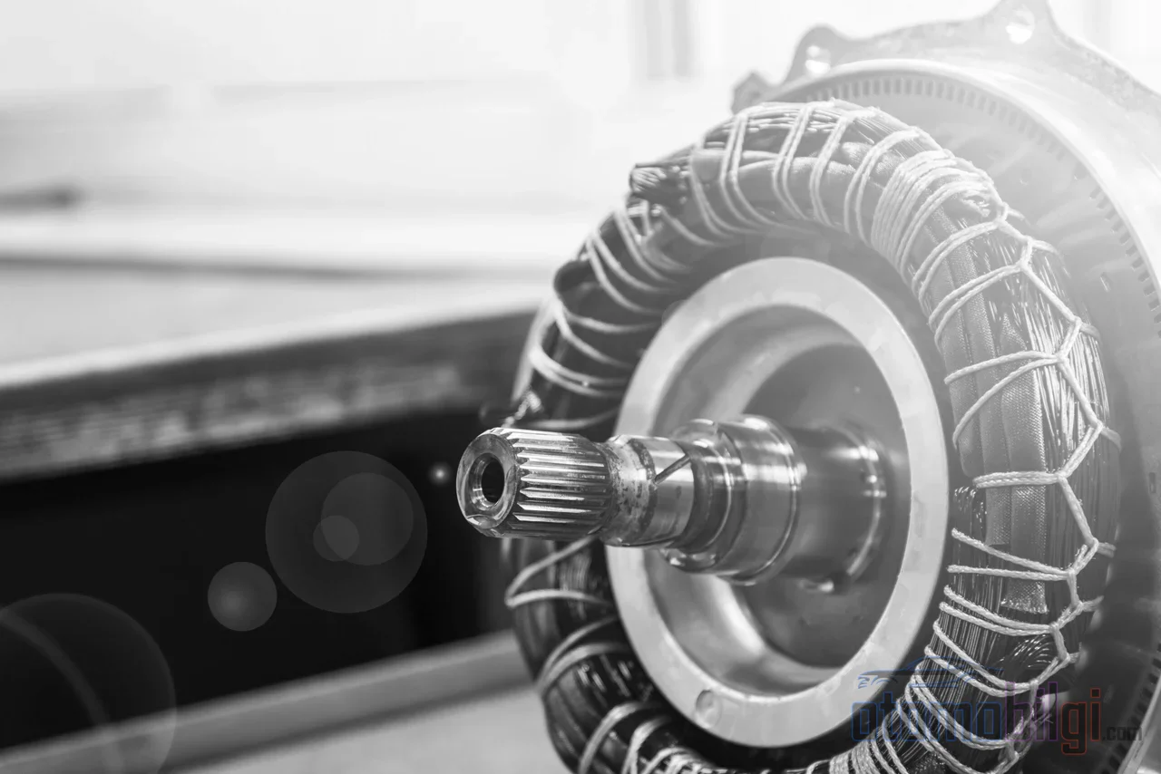
In SPM, torque production relies largely on a single mechanism: the tendency of the magnet field to align with the stator field, i.e. magnetic torque. In IPM, however, a second component comes into play. Due to the magnetic reluctance difference between the rotor's two axes, the rotor tends to rotate toward the position where the reluctance seen by the armature flux is reduced; the torque arising from this tendency is called reluctance torque.
In other words, the torque of an IPM motor is the sum of two components: the alignment torque of the magnets and the reluctance torque produced by saliency. This dual mechanism makes it possible to obtain more torque for the same current.
MTPA Control: More Torque from the Same Current
To fully take advantage of the dual torque benefit, IPM drives usually employ the MTPA (Maximum Torque Per Ampere) control strategy. The control algorithm continuously adjusts the current vector and targets the maximum possible torque with the lowest motor current. The result is less copper loss at every point of the efficiency map, and therefore less heat and longer range. The price of this is control complexity: MTPA and field weakening algorithms require more precise sensors and more computing power.
Field Weakening: The Way to Stay Efficient at High RPM
An electric vehicle motor must operate across a very wide RPM band, from city-speed starts up to highway speeds. Above base speed, the voltage applied to the motor reaches its peak; to reach higher speeds, the effective magnetic field acting on the rotor must be weakened. This technique is called field weakening, and its price is decreasing torque.
This is where the characters of the two designs diverge. The SPM's power-speed curve is roughly hyperbolic: it reaches near-constant power over a narrow speed band, then drops rapidly. The IPM, on the other hand, maintains its constant power region over a much wider speed range; its flux is structurally suited to weakening. For this reason, in applications such as electric vehicle drive motors that demand both high torque at low RPM and continuous power at high RPM, IPM is almost an inevitable choice.
The picture is similar on the efficiency side: SPM delivers high efficiency at low and constant speeds thanks to its simple magnetic circuit. IPM maintains its high efficiency across a wide speed range and is noticeably more efficient at high speeds. This wide operating region translates into range over a real driving cycle.
Mechanical Strength and Heat: Why Encapsulating the Rotor Pays Off
An electric vehicle motor rotates at speeds that can reach 15,000-20,000 RPM levels. The centrifugal force acting on surface-mounted magnets makes the bonding and sleeve solution more critical with every increase in RPM; in SPM, the mechanical strength limit restricts the motor's maximum safe speed. High temperature also increases the demagnetization risk for magnets exposed on the surface.
In IPM, since the magnets are trapped inside the rotor core, there is no such thing as breaking away from centrifugal force; the rotor is more robust and mechanical reliability increases. A similar logic applies on the heat side: core encapsulation provides a certain level of heat dissipation for the magnet and keeps the magnet at a lower temperature. In SPM motors, magnets directly exposed to the air gap have weaker heat dissipation. As a result, IPM machines show better overload capability than SPM at both low and high speeds.
IPM or SPM: Which Design for Which Job?
The advantages of IPM do not come free. The embedding process requires complex rotor geometry; it increases manufacturing cost and time, and demands advanced manufacturing techniques and strict quality control. Due to saliency, IPM produces significantly larger cogging torque and torque ripple than SPM; this ripple can conflict with cost and efficiency goals and requires a pragmatic engineering balance. SPM, on the other hand, offers a simple, inexpensive, and smooth-running structure; it remains a reasonable choice for tasks requiring a narrow operating band, such as low-speed pumps or home appliances.
| Feature | SPM (Surface-Mounted Magnet) | IPM (Interior Permanent Magnet) |
|---|---|---|
| Magnet position | Mounted on the rotor surface | Embedded in slots cut inside the rotor |
| Torque mechanism | Primarily magnetic torque | Magnetic + reluctance torque |
| Inductance behavior | Constant inductance | High Lq/Ld ratio (reluctance) |
| High-speed behavior | Narrow constant power region, power falling with speed | Constant power over a wide range, suitable for flux weakening |
| Mechanical strength | Limited; a sleeve may be required | High; inside the magnet core |
| Production and control | Simple and inexpensive | Complex, costly, requires advanced control |
| Typical usage | Home appliances, low-speed pumps | Electric vehicle drive motor |
There is also an argument in favor of IPM on the rare earth side: studies show that IPM requires only 66.7% of the magnet material needed by SPM for the same task. In the face of volatility in neodymium-iron-boron magnet prices, this is a direct cost advantage. In addition, thanks to high power and torque density, permanent magnet motors of similar performance can be produced at about one-third the size of conventional motors; The magnetic lifespan of the magnets is stated to be approximately 400 years.
The Rare Earth Debate and the Future
On the market side, the picture is clear: the rise of hybrid and electric vehicles grew IPM demand, and nearly all new-generation electric vehicle platforms of major automotive manufacturers use IPM as the main drive motor. The technology's development trajectory is also instructive: The discovery of neodymium-iron-boron magnets in the 1980s accelerated permanent magnet motors, SPM and IPM configurations took shape in the 1990s, and vector control and field-oriented control algorithms matured in the early 2000s.
On the other hand, rare earth supply and price volatility remain an ongoing cost concern for both designs. The search for alternative materials continues; there are academic studies on rare-earth-free drive motors with potential ferrite magnets, and the industry is experiencing discussions about a transition in this direction. However, as of today, permanent magnet motors remain by far the most common motor type in the electric vehicle market thanks to their high power and torque density.
Conclusion: Why Is the Magnet Buried Inside?
The short answer is this: By embedding its magnets in the rotor core, an IPM motor gains two sources of torque instead of one; thanks to the reluctance torque contribution and MTPA control, it extracts more work from the same current, provides constant power and high efficiency over a wide speed range through field weakening, makes the rotor mechanically safer at high speeds, and delivers the same performance with less magnet material. Except for narrow-band tasks where the simplicity of SPM is advantageous, the three fundamental demands of electric vehicle propulsion - high torque at low speed, a wide constant power region, and mechanical reliability - draw a one-sided picture in favor of IPM. The reason it has become the standard is this holistic superiority, and in return the manufacturing and control complexity that is paid for it.
Sources
- Surface Permanent Magnet Motors Vs Interior Permanent Magnet Motors - Tengye
- How to choose between surface permanent magnet motors and interior permanent magnet motors - Newland
- Comparison of internal and surface permanent-magnet motor topologies - IEEE
- Surface permanent magnet vs. interior PMSM analysis - Patsnap Eureka
- Reluctance Torque - ScienceDirect
- Field-Weakening Control - MATLAB & Simulink
- How to Build EV Motors Without Rare Earth Elements - IEEE Spectrum
- Why So Many Automakers Are Using 'IPM' Electric Motors - The Autopian