What Does a Torque Converter Replace the Clutch With in Automatics?
Share This Page
A torque converter is a hydrodynamic power transmission element that replaces the mechanical clutch in a classic automatic transmission, positioned between the engine and the transmission; it transmits torque without stalling the engine when the vehicle is stationary, and at launch it multiplies the torque produced by the engine at a ratio of 1.8:1 to 2.5:1 and establishes a lossless mechanical connection at cruising speed via the lock-up clutch. In short, it performs all three functions of a clutch in a single body: separating, smoothly connecting, and increasing torque when needed.
Highlights
- The stall speed ratio of typical automotive torque converters lies in the 1.8:1-2.5:1 range.
- The pump, turbine and stator trio creates the torque multiplication effect; torque capacity is proportional to the fifth power of the diameter.
- The first series-production lock-up clutch was seen in 1949 in the Packard Ultramatic; modern usage became widespread in the late 1970s under fuel economy pressure.
- During the clutch phase, the turbine rotates at approximately 90% of the pump speed; the remaining slip means heat and efficiency loss.
- ~64-72 km/h A brief shudder felt in this range is usually a sign of the lock-up clutch vibrating as it engages (shudder).
What Replaces the Clutch and Why Not a Full Clutch?
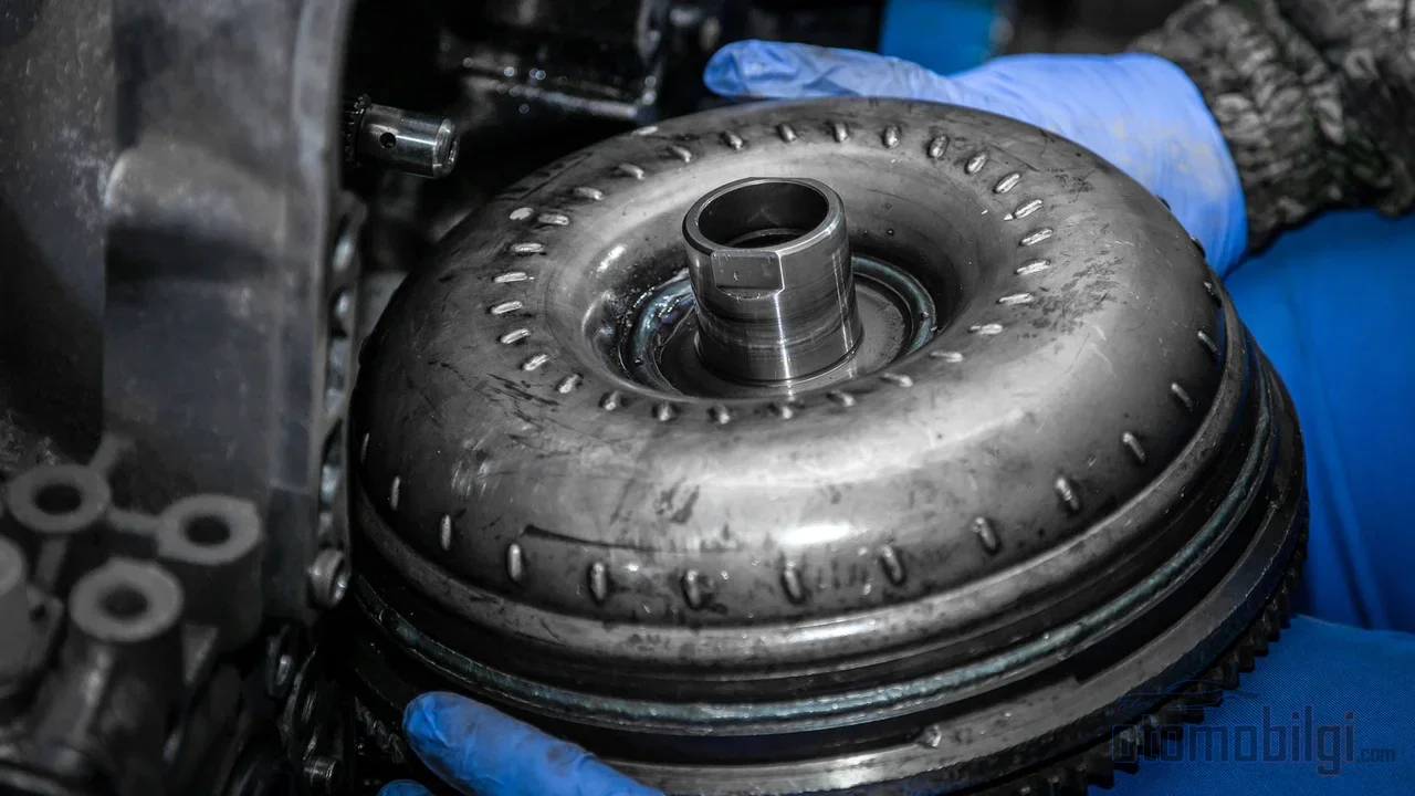
In a manual transmission, the driver establishes and cuts the connection between the engine and the transmission with the clutch pedal. In an automatic, this job is done not by a driver but by a closed bag bolted to the engine (mounted on the flywheel or flexplate): the fluid inside takes the rotational motion it receives from the engine and transfers it to the transmission's input shaft. This arrangement allows a vehicle in gear to remain stopped while the engine is running; the transmission stays freely disengaged while the engine keeps running.
So why fluid instead of a dry clutch? Because a mechanical clutch is either fully locked or slipping as long as there is contact - and when slipping, the lining heats up and wears out. In a fluid clutch, there is no such thing as contact point; slipping is the natural operating environment of the design, and it also naturally absorbs engine vibration. Moreover, a simple fluid clutch transmits torque with only a slight reduction. What sets the torque converter apart is its ability to increase torque when output speed is low thanks to the stator in between; in other words, it is an element that forces itself to act like an adaptive gearbox when rotational speed is low.
This is also the secret of how a computer-controlled automatic can make decisions independently of the driver's pedal: the converter offers a controlled and safe slip window that a clutch cannot provide; the transmission never encounters an unexpected mechanical shock at any moment.
Pump, Turbine and Stator: How Is Torque Multiplied?
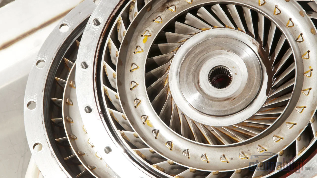
The converter has three rotating/non-rotating components. The pump (impeller) is connected to the engine and works like a centrifugal pump: as it rotates, it slings fluid outward, creating a vacuum at the center that draws in new fluid. The expelled fluid strikes the turbine's curved blades, changes direction, and rotates the turbine, transmitting power to the transmission input shaft.
The real intelligence is hidden in the third element. The fluid leaving the turbine moves opposite to the engine's direction of rotation; in a simple fluid coupling, this returning energy is merely converted into heat. The stator, positioned between the pump and the turbine, redirects this fluid and feeds the pump at an optimal angle. In this way, the energy of the returning fluid is recovered and added to the output torque on top of the torque produced by the engine. To explain it in terms of mechanical balance: the fluid leaving the turbine strikes the stator, and therefore applies a torque opposite in direction to the housing to which the stator is fixed; this difference is directly reflected on the output side as a torque gain.
Two details are critical from an engineering standpoint. The first is blade geometry: inclined, curved blades are used in the turbine and stator, and small variations in geometry significantly change performance. The second is size: the converter's equations of motion are based on Euler's turbomachine equation dating back to the 18th century, and since the characteristics depend on the 5th power of the radius, torque capacity is theoretically proportional to fluid density, the square of speed, and the fifth power of diameter. Increasing the diameter slightly increases the capacity far more.
It is also important that the stator does not remain idle: the stator is mounted on a one-way clutch . During launch and acceleration, the fluid pushes it from behind and the stator remains fixed; when the coupling phase is reached, fluid pressure decreases and the stator begins to rotate freely - rotation in the reverse direction is prevented by the one-way clutch.
Three Operating Phases: Stall, Acceleration, and Coupling
The clearest way to understand the converter's behavior is to read it in three phases. In the stall phase , a gear is engaged, the brakes hold the vehicle, the turbine is not rotating but the pump rotates with the engine; with sufficient input power, the maximum torque multiplication is achieved here, and this ratio is called the stall ratio. In automotive applications, the typical value is 1.8:1-2.5:1; in industrial, marine, and heavy-duty special converters, this ratio goes up to 5.0:1. The total multiplication effect at stall can be surprising: when a 2.46:1 transmission ratio is combined with a 2.2:1 stall ratio, a total multiplication of 5.41:1 goes to the wheels at a complete standstill; when the coupling phase is reached, this number drops to 2.73:1.
In the acceleration phase , as the load increases, the speed difference between the pump and the turbine is still large; torque multiplication exists but is below the stall value. In this region, the spiraling vortex flow of the fluid from the pump to the stator and from there to the turbine is dominant - this is the regime where torque multiplication peaks.
The coupling phase is entered when the turbine reaches approximately 90% of the pump speed: while the pump turns 10 revolutions, the turbine turns 9, meaning a slip of approximately 1.11:1 is typical. At this point, torque multiplication effectively ends; the spiral motion of the fluid gives way to rotary flow releases and the stator begins to spin freely. There is a clear trade-off between torque multiplication and efficiency: converters with high stall ratios operate less efficiently around clutch engagement speed. Those seeking performance must choose the multiplying character, while those seeking economy must choose the character with less slip.
Lock-up Clutch: The Second Clutch That Eliminates Slip
Fluid-drive transmission has nothing supernatural about it: slip means direct efficiency loss and heat. The lock-up clutch inside the converter exists precisely for this reason. It mechanically locks the turbine directly to the impeller during cruising, transmitting all the power through the mechanical path; fluid losses and heat generation disappear, revs drop slightly, and a more direct power line to the wheels is established.
Its history is interesting. The first automotive application dates back to the Packard Ultramatic transmission in 1949 : the vehicle locked up once it reached cruising speed and released when the throttle was pressed or while slowing down. It was also seen in some Borg-Warner transmissions in the 1950s, then abandoned due to cost and complexity. When priorities shifted to fuel efficiency in the mid-1970s, the idea returned; Chrysler introduced its modern version in 1978 . In technical publishing, the widespread modern-era use of locking converters is sometimes dated to 1981
; the difference stems from the first application and mass adoption coinciding with different periods. Today's debate is about calibration: engaging the lock-up as early as possible saves fuel in city driving, but means giving up the converter's torque multiplication advantage. In high-performance street cars, lock-up is usually positioned not as an economy accessory but as the element that makes a strong converter livable in daily use. As the number of gears increases, the converter's multiplication burden decreases, so early and frequent lock-up has become standard in modern 6-10 speed automatics; in contrast, in traditional automatics the converter deliberately remains unlocked for most of the drive - while in CVTs it is nearly always locked above roughly 8 km/h, because there the torque multiplication job already belongs to the variator.
Effect on Driving Character and Known Failure Modes
The converter is the silent hero that defines the character of an automatic. It ensures smoothness when the lock-up clutch engages; in the unlocked phases, it absorbs engine shake and torsional vibrations through the fluid. But this damping ability is not infinite: torsional vibrations in the drivetrain are the main engineering constraint limiting how early lock-up can be engaged. When the lock-up clutch grabs suddenly instead of slipping, the resulting stick-slip behavior can spread vibrations throughout the entire drivetrain - this is the event that disrupts the driver's perception of comfort.
The most commonly heard complaint is converter shudder: usually ~64-72 km/h in the band, a brief jolt felt when the clutch locks up. In partial lockup, it occurs when the clutch operates by gripping rather than slipping; a worn clutch lining and dirty/degraded ATF are the main causes, and in most cases renewing the transmission fluid solves the problem. The complaint cutting off when you press the gas pedal or touch the brake is a typical clue: when the converter opens, the slipping zone disappears. In practice, the true source of most lockup converter failures is not even the converter itself; it appears in the valve body, the electronic controls, or the engagement solenoid.
There are also more serious failure modes:
- Overheating: Attempts to get out by rocking back and forth in snow or mud keep the converter in stall mode for a long time; modern blade geometry minimizes fluid speed at low rpm, reducing this risk but not eliminating it.
- Stator clutch lockup: When the stator stops free-wheeling, the converter operates at very low efficiency in the coupling phase; a serious increase in fuel consumption is the classic symptom.
- Stator clutch breakage: Sudden power applications (such as events like a neutral start at the moment of cranking) can break the one-way clutch.
A Brief History: How the Converter Built the Automatic?
The torque converter's rise in automotive history accelerated after World War II, with the Hydra-Matic experience in military vehicles. 1948, with Buick Dynaflow , fluid couplings began to be replaced by torque converters; Dynaflow was an ambitious design that based the entire torque multiplication of its single gear on a five-element converter. It was followed by 1949 Packard Ultramatic and 1950 Chevrolet Powerglide : in these two-speed transmissions, the converter largely took on the job of torque multiplication.
In the 1950s a balance was struck: BorgWarner's three-speed automatics and designs based on the Simpson compound planetary gear set, such as the Chrysler TorqueFlite, made the converter an indispensable component of automatics. Multi-element converter experiments (Buick Triple Turbine Dynaflow, Chevrolet Turboglide) were abandoned due to low efficiency; their place was taken by arrangements of a three-speed transmission plus a three-element converter. An interesting GM detail of the era was the variable-angle stator: when the gas was pressed suddenly, the stator's angle of attack changed, sacrificing efficiency in favor of increased torque multiplication - a mechanical ancestor of today's adaptive calibration philosophy.
Frequently Asked Questions
How does a torque converter multiply torque?
The fluid exiting the turbine flows opposite to the engine's direction of rotation; the stator redirects this fluid toward the pump's direction of rotation, recovering its energy. In this way, more torque reaches the output shaft than the engine produces; at launch, this ratio is between 1.8:1 and 2.5:1.
Why do automatics have a torque converter instead of a clutch?
Because the converter turns slippage into an operating mode rather than a fault: it allows the vehicle to remain stopped while in gear, absorbs jolts, multiplies torque, and performs all three tasks continuously and safely without driver intervention. The mechanical clutch in a manual transmission does only one of these-making and breaking the connection.
What does converter shudder feel like?
It is a brief shudder that resembles a slight wheel imbalance but is felt only in a certain speed range (usually 64-72 km/h) and at the moment of lock-up. It becomes noticeable at light throttle and mostly disappears when pressure on the accelerator increases; it can be eliminated with an oil change.
Summary: The Converter's Three Tasks in One Sentence
In a classic automatic, the torque converter handles the clutch's disconnecting function with fluid, the torque multiplication function with the stator, and the efficiency demand with the lock-up clutch. This mechanism, which multiplies torque up to 2 times at stall, lives with a 10% slip in the coupling phase, and eliminates slippage when locked, is the single component that carries both the comfort and economy of the automatic transmission in the same body.
Sources
- Torque converter - Wikipedia
- Torque Converters: The Backbone of Modern Automotive Technology - Gears Magazine
- Understanding Torque Converters - Hot Rod
- Torque converter torque multiplication - Engineering Stack Exchange
- Torque converter clutch - x-engineer.org
- The Evolution of Lock-Up Torque Converters - Motor State
- What is Torque Converter Shudder? - Roadrunner Converters
- The torque converter can of worms - Transmission Digest
- Aggressive Torque Converter Clutch Slip Control (Otanez 2009) - JSTOR